X20 system modules • Analog input modules • X20AI4322
X20 system User's Manual 3.10
273
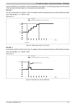
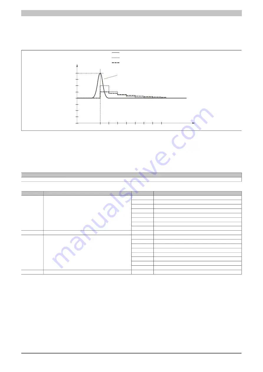
Example 2
A disturbance interferes with the input value. The diagram shows the calculated value with the following settings:
Input ramp limitation = 0
Filter level = 2 or 4
0
8000
16000
t [ms]
1
2
3
4
5
6
7
8
Input value
Calculated value: Filter level 2
Calculated value: Filter level 4
Disturbance (spike)
Figure 107: Calculated value during disturbance
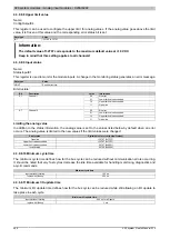
4.3.10.8.6 Configuring the input filter
Name:
ConfigOutput01
This register is used to define the filter level and input ramp limitation of the input filter.
Data type
Value
USINT
See bit structure.
Bit structure:
Bit
Description
Value
Information
000
Filter switched off
001
Filter level 2
010
Filter level 4
011
Filter level 8
100
Filter level 16
101
Filter level 32
110
Filter level 64
0 - 2
Defines the filter level
111
Filter level 128
3
Reserved
0
000
The input value is used without limitation
001
Limit value = 0x3FFF (16383)
010
Limit value = 0x1FFF (8191)
011
Limit value = 0x0FFF (4095)
100
Limit value = 0x07FF (2047)
101
Limit value = 0x03FF (1023)
110
Limit value = 0x01FF (511)
4 - 6
Defines the input ramp limitation
111
Limit value = 0x00FF (255)
7
Reserved
0
Summary of Contents for X20 System
Page 2: ......

