X20 system modules • Analog input modules • X20AP31x1
322
X20 system User's Manual 3.10
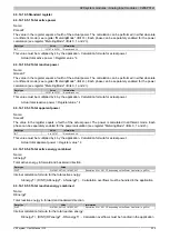
The user can configure which one to use for displaying the status.
Phase angle
The phase angle is calculated based on the zero-crossing detection.
Frequency
Frequency measurement is based on Phase A. If A fails, then Phase C is used. If both A and C fail, then Phase
B is used.
Temperature
The Chip-Junction temperature is measured approximately every 100 ms using the sensor integrated in the trans-
former.
THD+N - Sum of interference power of the harmonic (THD) + interference power of the noise (N)
The THD+N measurement is used to monitor the percentage of harmonics in the network.
If this percentage falls below 10%, then an accuracy of 0.01% can no longer be guaranteed.
This is calculated as follows: (SQR (RMS
total
^2 - RMS
fundamental wave
^2)) / RMS
fundamental wave
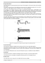
Fourier analysis
The harmonic component from the 2nd to the 31st harmonic is calculated for voltage and current and the THD
(Total Harmonic Distortion) of each phase.
The DFT period is 0.5 s. This corresponds to a resolution of 2 Hz. The input samples are recorded at a sampling
rate of 8 kHz and can be optionally multiplied with a "Hann window" before being evaluated. This is initiated when
requested by the application.
X
X
Frequency
components for
fundamental wave
and
harmonics
Post-
processing
Digital
Fourier
Transformation
Percentage-based
components of
fundamental wave
and
harmonics
Hanning
window
Scaling
Input
samples
from the
DSP processor
Interface for automatic
output of values
Mains frequency
Sampling frequency
Analysis of harmonics
Interface to the
oversampling
buffer
Figure 138: Diagram of Fourier analysis
Summary of Contents for X20 System
Page 2: ......

