X20 system modules • Analog output modules • X20AO4632-1
X20 system User's Manual 3.10
491
1
X
20
A
O
4
63
2-
1
2
AO + 3 I
AO + 3 U
AO - 3 U/I
AO + 1 I
AO + 1 U
AO - 1 U/I
AO + 4 I
AO + 4 U
AO - 4 U/I
AO + 2 I
AO + 2 U
AO - 2 U/I
3 4
r
e
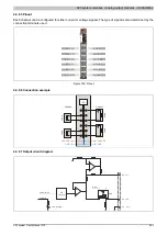
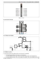
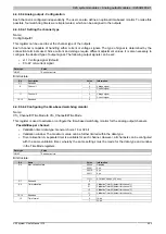
Figure 191: Pinout
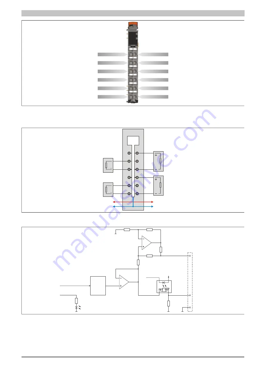
4.4.9.6 Connection example
GND
+24 VDC
GND
+24 VDC
AO
+
+
Voltage
Current
Lo
ad
Lo
ad
Lo
ad
Lo
ad
4.4.9.7 Output circuit diagram
AO + x I
AO + x U
AO - x U/I
SSR
Reset
D/A
converter
Output value
I/O status
LED (orange)
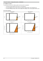
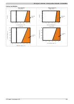
4.4.9.8 Module operation
To ensure proper operation, the following items must be taken into consideration:
•
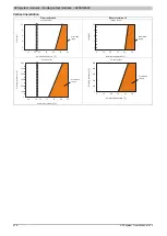
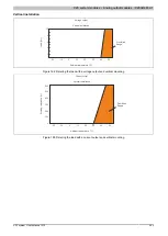
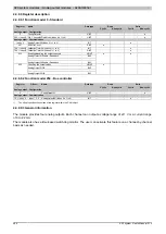
The following derating listings must be taken into consideration
•
For mixed operation with one current output, the average of both derating curves should be used
•
For mixed operation with two or three current outputs, the derating for the current outputs should be used
Summary of Contents for X20 System
Page 2: ......


