X20 system modules • Analog output modules • X20AO4635
504
X20 system User's Manual 3.10
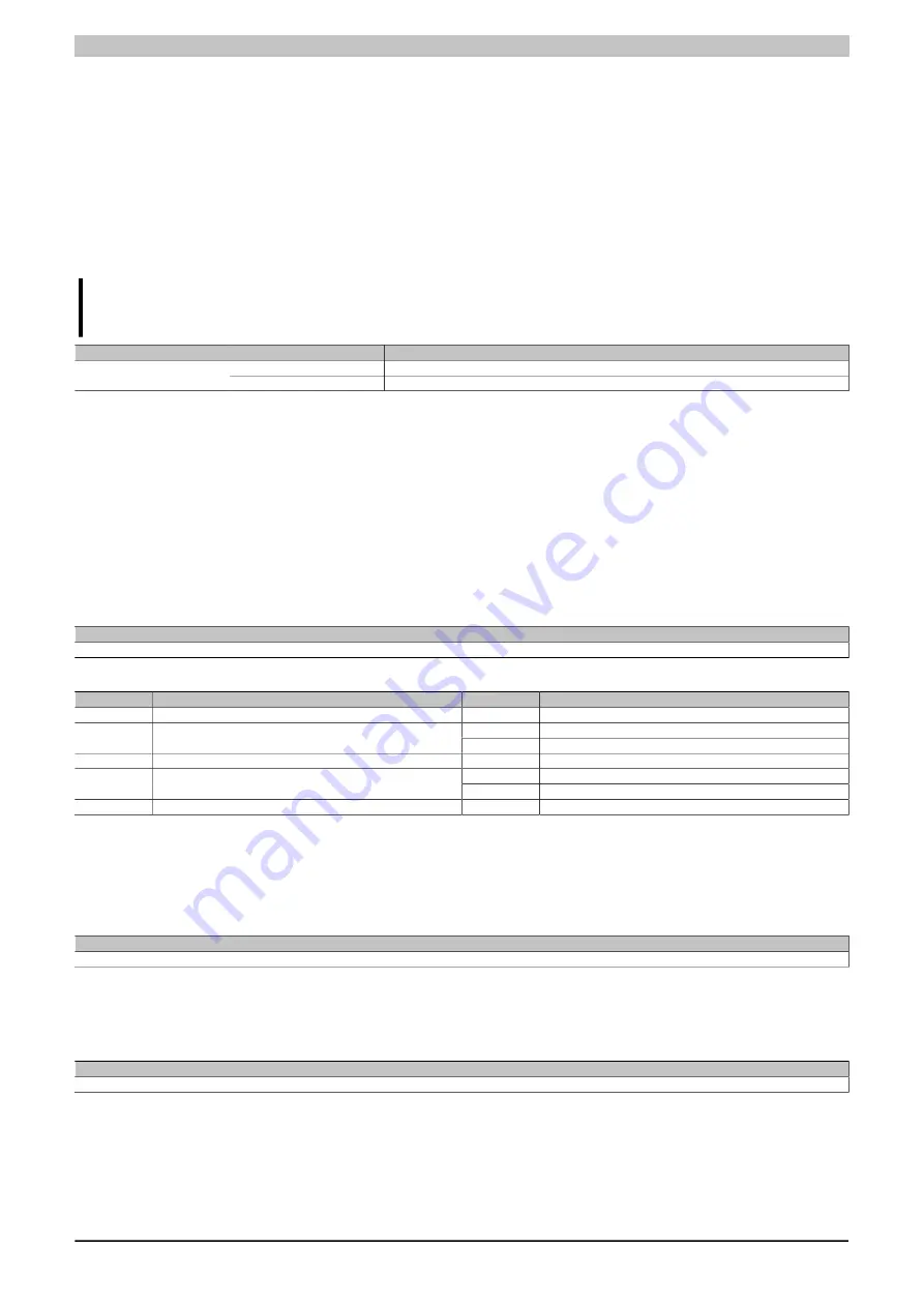
4.4.10.9.3 Analog outputs
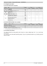
Each channel can be configured for either current or voltage signals. The type of signal is also determined by the
connection terminals used.
4.4.10.9.3.1 Output values of the analog outputs
Name:
AnalogOutput01 to AnalogOutput04
These registers provide the standardized output values. Once a permitted value is received, the module outputs
the respective current or voltage.
Information:
The value "0" disables the channel status LED.
Data type
Value
-32767 to 32767
Voltage; Bus controller default setting: 0
INT
0 to 32767
Current
4.4.10.9.3.2 Setting the channel type
Name:
ConfigOutput01
This register can be used to set the channel type of the outputs.
Each channel is capable of handling either current or voltage signals. The type of signal is determined by the
connection terminals used. Since current and voltage require different adjustment values, it is also necessary to
configure the desired type of output signal. The following output signals can be set:
•
±10 V voltage signal (default)
•
0 to 20 mA current signal
Data type
Value
USINT
See bit structure.
Bit structure:
Bit
Description
Value
Information
0 - 7
Reserved
0
0
Voltage signal
8
Channel 1
1
Current signal
...
...
0
Voltage signal
11
Channel 4
1
Current signal
12 - 15
Reserved
0
4.4.10.9.4 Minimum cycle time
The minimum cycle time defines how far the bus cycle can be reduced without communication errors occurring.
It should be noted that very fast cycles decrease the idle time available for handling monitoring, diagnostics and
acyclic commands.
Minimum cycle time
200 µs
4.4.10.9.5 Minimum I/O update time
The minimum I/O update time defines how far the bus cycle can be reduced while still allowing an I/O update to
take place in each cycle.
Minimum I/O update time
200 µs
Summary of Contents for X20 System
Page 2: ......

