X20 system modules • Bus controllers • X20BC0088
548
X20 system User's Manual 3.10
Product ID
X20BC0088
Power consumption
Bus
2.0 W
Additional power dissipation caused by the actua-
tors (resistive) [W]
-
Electrical isolation
Fieldbus - X2X Link
Yes
Fieldbus - I/O
Yes
Certification
CE
Yes
cULus
Yes
cCSAus HazLoc Class 1 Division 2
Yes
ATEX Zone 2
Yes
KC
Yes
GOST-R
Yes
Interfaces
Fieldbus
EtherNet/IP adapter (slave)
Design
2x shielded RJ45 port (switch)
Cable length
Max. 100 m between two stations (segment length)
Transfer rate
10/100 Mbit/s
Transmission
Physical interfaces
10 BASE-T/100 BASE-TX
Half-duplex
Yes
Full-duplex
Yes
Autonegotiation
Yes
Auto-MDI / MDIX
Yes
Min. cycle time
1)
Fieldbus
1 ms
X2X Link
500 μs
Synchronization between bus systems possible
No
Operating conditions
Mounting orientation
Horizontal
Yes
Vertical
Yes
Installation at altitudes above sea level
0 to 2000 m
No limitations
>2000 m
Reduction of ambient temperature by 0.5°C per 100 m
Protection in accordance with EN 60529
IP20
Environmental conditions
Temperature
Operation
Horizontal installation
-25 to 60°C
Vertical installation
-25 to 50°C
Derating
-
Storage
-40 to 85°C
Transport
-40 to 85°C
Relative humidity
Operation
5 to 95%, non-condensing
Storage
5 to 95%, non-condensing
Transport
5 to 95%, non-condensing
Mechanical characteristics
Note
Order 1x X20TB12 terminal block separately
Order 1x X20PS9400 or X20PS9402 power supply module separately
Order 1x X20BB80 bus base separately
Spacing
2)
37.5
+0.2
mm
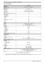
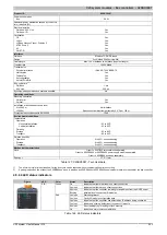
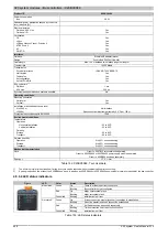
Table 152: X20BC0088 - Technical data
1)
The minimum cycle time defines how far the bus cycle can be reduced without communication errors occurring.
2)
Spacing is based on the width of the X20BB80 bus base. In addition, an X20PS9400 or X20PS9402 supply module is always required for the bus controller.
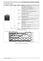
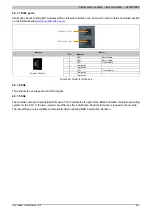
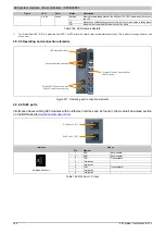
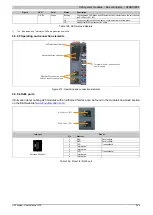
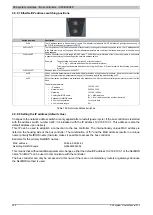
4.5.9.4 LED status indicators
Figure
LED
Color
Status
Description
On
There is at least one client connection.
Green
Blinking
Bus controller not yet configured.
On
Major unrecoverable fault.
Red
Blinking
Major recoverable fault.
Mod status
1)
Green/red
Blinking
Initialization / self test
On
At least one active master (scanner) connection is established.
Green
Blinking
No active master (scanner) connection established.
On
An IP address has been used repeatedly.
Red
Blinking
Timeout occurred on at least one connection.
Net status
1)
Green/red
Blinking
Initialization / self test
Table 153: LED status indicators
Summary of Contents for X20 System
Page 2: ......

