X20 system modules • Bus controllers • X20BC00E3
556
X20 system User's Manual 3.10
4.5.10.7 Node number switches
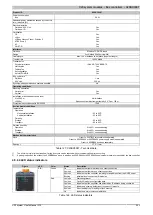
The bus controller has 2 node number switches. The bus controller can be set to different operating modes using
certain, pre-defined switch positions. They can also be used to configure various additional parameters (PROFINET
device name, DHCP mode, etc.).
Switch position
Description
0x00
All parameters are loaded from flash memory: Default PROFINET initialization via the DCP protocol (factory state)
0x01 - 0xEF
These switch positions generate a valid PROFINET device name. This name is composed as follows: "brpnXXX".
XXX refers to the decimal value of the node number switch position. The system automatically adds any necessary
leading zeros.
0xF0
Clears flash (see 4.5.10.8 "Erasing flash memory" on page 556)
0xF1 - 0xFD
Reserved, switch position not permitted
0xFE
IP address via DHCP server
0xFF
All parameters set to default: PME mode
Table 160: X20BC00E3 - Node numbers
Default PROFINET factory state - Node number switch position 0x00
Parameter
Value
IP address
0.0.0.0
Subnet mask
0.0.0.0
Gateway
0.0.0.0
PROFINET device name
"" ... no factory default name
Table 161: Factory settings: Node number switch position 0x00
Default parameters - Node number switch position 0xFF
Parameters cannot be changed by the master in node switch position 0xFF.
Parameter
Value
IP address
192,168,100.1
Subnet mask
255,255,255.0
Gateway
192,168,100,254
PROFINET device name
x20bc00e3
Table 162: Default parameters: Node number switch position 0xFF
4.5.10.8 Erasing flash memory
Erasing flash memory using switch position 0xF0 returns the bus controller to its factory state.
Procedure
1. Turn off the power supply to the bus controller.
2. Set the node number to 0xF0.
3. Turn the power supply to the bus controller back on.
4. Wait until the "MS" LED flashes green for 5 s. The node number switch must be set to 0x00 and then back
to 0xF0 within this time window of 5 seconds (rotate the top switch).
5. Wait until the "MS" LED blinks with a red double-flash (flash has been cleared).
6. Turn off the power supply to the bus controller.
7. Set the desired node number (0x00 - 0xEF)
8. Turn the power supply to the bus controller back on.
9. The bus controller boots with the configured node number.
4.5.10.9 Web interface
The integrated Web interface gives the user an overview of the bus controller's network parameters, the configured
I/O modules and the switch configuration. The starting page includes information regarding specific bus controller
settings such as IP address, host name and the PROFINET device name. In addition, the web page provides
Summary of Contents for X20 System
Page 2: ......


