X20 system modules • Bus controllers • X20BC0143-10
564
X20 system User's Manual 3.10
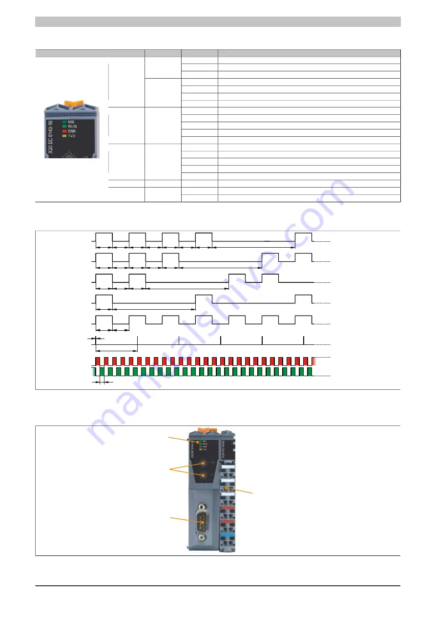
4.5.12.4 LED status indicators
Figure
LED
Color
Status
Description
Off
No power supply
Flashing
5 s window for deleting all configuration settings
Green
On
Boot procedure OK, I/O modules OK
Double flash
Successfully erased flash memory
Triple flash
Successfully saved transfer rate
Quad flash
Successfully saved configuration
MS
1)
Red
On
I/O modules: Error message or incorrect configuration
Off
No power supply
Single flash
STOP mode
Triple flash
Firmware download in progress
Blinking
PREOPERATIONAL mode
RUN
Green
On
OPERATIONAL mode
Off
No power supply or everything is OK
Single flash
CAN warning limit reached
Double flash
Node guarding / heartbeat error
Blinking
Invalid node number or configuration
ERR
Red
On
Bus errors: Bus off
RUN/ERR
Green/red
Flickering
Transfer rate detection in progress
Off
The bus controller is not transmitting any data via the CANopen fieldbus
TxD
Yellow
On
The bus controller is transmitting data via the CANopen fieldbus
Table 170: LED status indicators
1)
The "MS" LED is a green/red dual LED. The LED blinks red several times immediately after startup. This is a boot message, however, and not an error.
50
500
3
200
200
1000
200
200
200
200
1000
200
200
200
1000
200
200
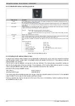
All times in ms
grün/rot
Flickering
blitzend
blinkend
single Flash
double Flash
triple Flash
200
200
200
1000
200
200
quad Flash
200
200
Figure 218: Status LEDs - Blinking patterns
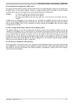
4.5.12.5 Operating and connection elements
LED status indicator
CANopen interface
Node number switches
Terminal block for bus controller
and I/O supply
Figure 219: Operating and connection elements
Summary of Contents for X20 System
Page 2: ......


