X20 system modules • Counter modules • X20DC1176
X20 system User's Manual 3.10
655
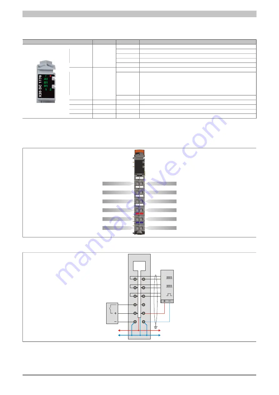
4.11.3.4 LED status indicators
For a description of the various operating modes, see the 2.11.1 "re LEDs" section.
Figure
LED
Color
Status
Description
Off
No power to module
Single flash
RESET mode
Double flash
BOOT mode (during firmware update)
1)
Blinking
PREOPERATIONAL mode
r
Green
On
RUN mode
Off
No power to module or everything OK
Single flash
The encoder monitor has detected a line fault on the encoder inputs. The status
bits must be evaluated in order to provide a more detailed definition of this error.
The following error states are detected:
•
Open line
•
Short-circuit or voltage level too low
e
Red
On
Error or reset status
A1
Green
Input state of counter input A
B1
Green
Input state of counter input B
R1
Green
Input state of reference pulse R
1 - 2
Green
Input state of the corresponding digital input
1)
Depending on the configuration, a firmware update can take up to several minutes.
4.11.3.5 Pinout
Shielded cables must be used for all signal lines.
1
X
20
D
C
1
17
6
2
A
B
R
A\
B\
R\
DI 1
Encoder 24 V+
GND
DI 2
Encoder 5 V+
GND
r
e
A1
B1
R1
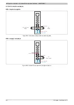
4.11.3.6 Connection example
GND
+24 VDC
GND
+24 VDC
DC
C
ou
nt
er
1
Se
ns
or
1
A
A\
B
B\
R
R\
Summary of Contents for X20 System
Page 2: ......


