X20 system modules • Digital input modules • X20DI4371
966
X20 system User's Manual 3.10
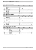
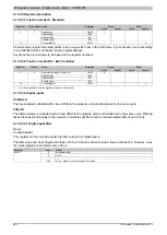
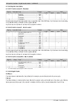
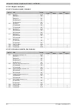
4.13.6.9 Register description
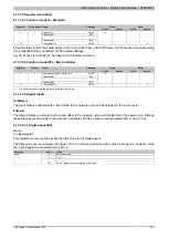
4.13.6.9.1 Function model 0 - Standard
Read
Write
Register
Fixed offset Name
Data type
Cyclic
Acyclic
Cyclic
Acyclic
USINT
DigitalInput01
Bit 0
...
...
0
1
DigitalInput04
Bit 3
●
18
-
USINT
●
Fixed modules require their data points to be in a specific order in the X2X frame. Cyclic access occurs according
to a predefined offset, not based on the register address.
Acyclic access is continues to be based on the register numbers.
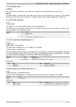
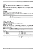
4.13.6.9.2 Function model 1 - Event counter
Read
Write
Register
Fixed offset Name
Data type
Cyclic
Acyclic
Cyclic
Acyclic
Input status of digital inputs 1 to 4
USINT
DigitalInput01
Bit 0
...
...
0
1
DigitalInput04
Bit 3
●
4
2
UINT
●
6
4
UINT
●
8
6
UINT
●
10
8
UINT
●
USINT
ResetCounter01
Bit 0
...
...
12
0
ResetCounter04
Bit 3
●
18
-
USINT
●
14
-
USINT
●
Fixed modules require their data points to be in a specific order in the X2X frame. Cyclic access occurs according
to a predefined offset, not based on the register address.
Acyclic access is continues to be based on the register numbers.
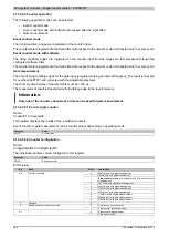
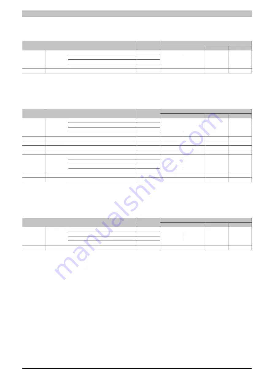
4.13.6.9.3 Function model 254 - Bus Controller
Read
Write
Register
Offset
1)
Name
Data type
Cyclic
Acyclic
Cyclic
Acyclic
Input status of digital inputs 1 to 4
USINT
DigitalInput01
Bit 0
...
...
0
0
DigitalInput04
Bit 3
●
18
-
USINT
●
1)
The offset specifies where the register is within the CAN object.
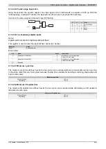
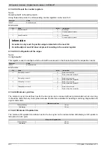
4.13.6.9.4 Digital inputs
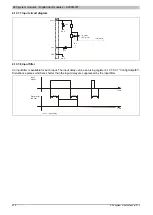
Unfiltered
The input state is collected with a fixed offset to the network cycle and transferred in the same cycle.
Filtered
The filtered status is collected with a fixed offset to the network cycle and transferred in the same cycle. Filtering
takes place asynchronously to the network in multiples of 200 µs with a network-related jitter of up to 50 µs.
Summary of Contents for X20 System
Page 2: ......

