X20 system modules • Other functions • X20DS438A
X20 system User's Manual 3.10
2247
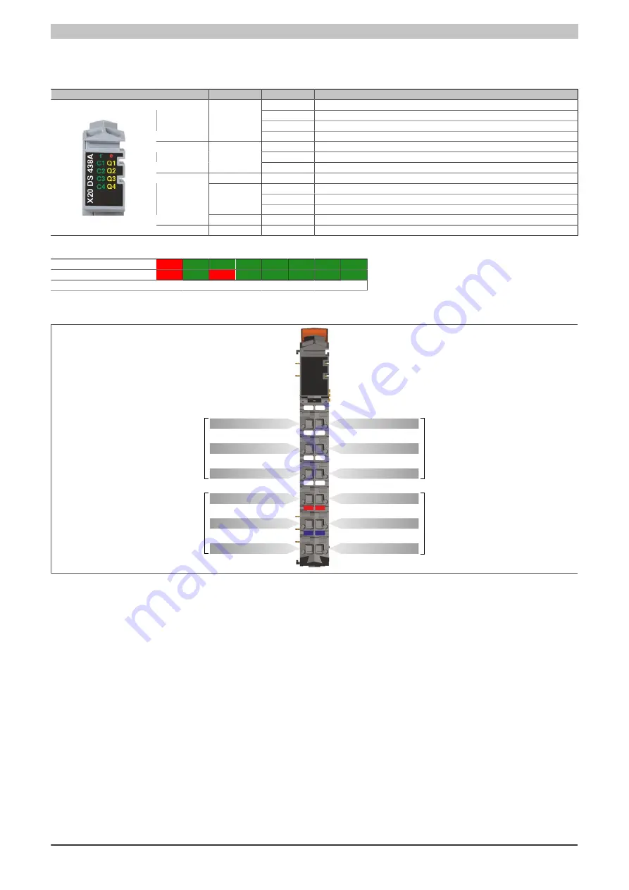
4.26.5.4 LED status indicators
For a description of the various operating modes, see the 2.11.1 "re LEDs" section.
Figure
LED
Color
Status
Description
Off
No power to module
Single flash
RESET mode
Blinking
PREOPERATIONAL mode
r
Green
On
OPERATE mode
Off
No power to module or everything OK
On
Error or reset status
e
Red
Double flash
One of the following errors has curred:
Red
On
Overload on the supply or on the channel's C/Q line
Off
Interface in SIO mode
Single flash
Channel in OPERATE mode, no IO-Link communication
Green/Red
Double flash
Channel in OPERATE mode, error on inspection level
C1 - C4
Green
On
Channel in OPERATE mode, IO-Link communication active
Q1 - Q4
Orange
Input/output state of corresponding IO-Link interface
Blink times of LEDs C1 through C4 for single and double flash.
Single flash
Double flash
1 second
4.26.5.5 Pinout
X
20
D
S
4
38
A
r
e
+24 VDC 4
+24 VDC 3
GND
GND
C1
C4
Q1
C2
Q2
C3
Q3
Q4
C/Q 1
+24 VDC 1
GND
C/Q 3
C/Q 2
+24 VDC 2
GND
C/Q 4
C
ha
nn
el
1
C
ha
nn
el
3
C
ha
nn
el
2
C
ha
nn
el
4
Summary of Contents for X20 System
Page 2: ......


