X20 system modules • Other functions • X20DS438A
X20 system User's Manual 3.10
2259
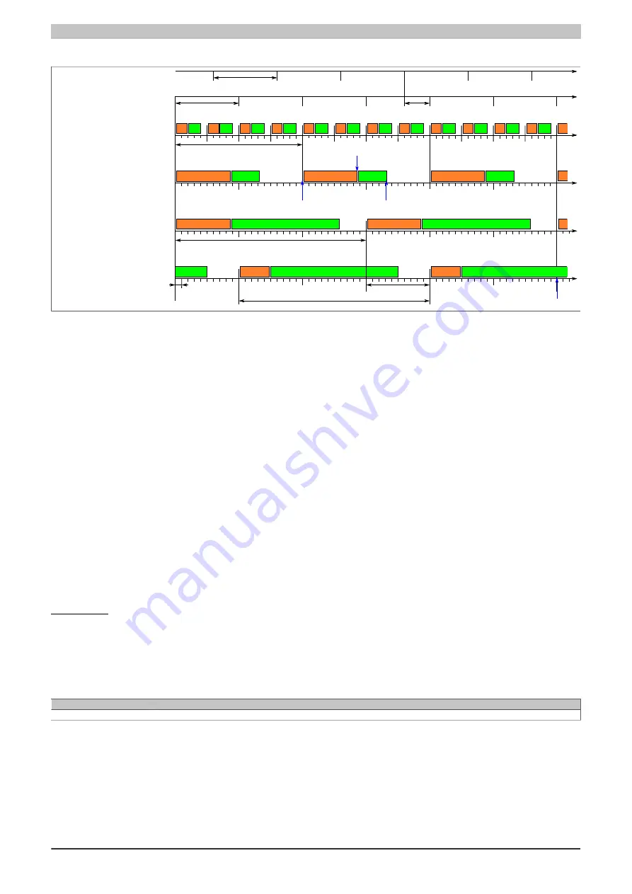
Example of a configuration
X2X cycle 1 ms
Timer cycle 1 ms
Timer offset (400 μs)
Synchronization cycle 2 ms
CycleRequesetEndNettime02
CycleStartNettime02
CycleEndNettime02
Synchronization cycle 3 ms
100 μs
Cycle offset
3 ms
Synchronization time
Multiple = 2
Divisor = 4
Offset = 0
Cycle time = 0.5 ms
Multiple = 2
Divisor = 1
Offset = 0
Cycle time = 2 ms
Multiple = 3
Divisor = 1
Offset = 0
Cycle time = 3 ms
Multiple = 3
Divisor = 1
Offset = 1
Cycle time = 3 ms
Channel 1:
Channel 2:
Channel 3:
Channel 4:
X2X cycle
Timer cycle
The module timer in this example
•
The duration of the module timer period was not defined explicitly. In this case, it corresponds to the X2X
Link cycle time.
•
An offset of 400 µs was applied to the module timer; i.e. the module timer cycle begins 400 µs after the
X2X Link cycle.
IO-Link communication in this example
•
The parameters Multiple and Divisor produce a channel-specific cycle time for IO-Link communication.
•
Channels 1 and 2 have a shared synchronization cycle of 2 ms.
Channels 3 and 4 have a shared synchronization cycle of 3 ms, which is shifted due to the offset.
•
Channels start their query together at the beginning of a shared synchronization cycle.
•
The IO-Link cycle of the fourth channel was delayed with an offset of 1 ms.
•
All channels have a shared synchronization cycle of 6 ms.
Free-running (asynchronous) mode
If the IO-Link and X2X cycle times cannot be synchronized, then the IO-Link cycle time can be defined explicitly.
IO-Link communication then runs independently of the module timer and X2X cycle. Except for CycleEndNettime,
no other net time data points can be used. The cycle times of free-running IO-Link channels are defined directly
via the corresponding registers. However, deviations may occur if the module's resources are exhausted.
TimerCycle
Name:
CfO_TimerCycle
This register can be used to configure synchronous IO-Link communication. If the module timer is not meant to be
operated with the same cycle, then it is possible to define the period length of the module timer in µs using this
register. This allows channels to be synchronized with one another even if using a very unusual X2X cycle time.
Data type
Value
UDINT
0 to 4,294,967,295
Summary of Contents for X20 System
Page 2: ......


