Technical data • Complete system
Chapter 2
Technical data
Panel PC 2100 swing arm user's manual V1.12
27
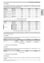
2.2.1.4 Ambient temperature for storage and transport
The following table provides an overview of the minimum and maximum ambient temperatures for storing and
transporting individual components.
Display type
Model number
Storage
Transport
15.0" single-touch
5AP92D.1505-0x
-25 to 80°C
-25 to 80°C
19.0" single-touch
5AP92D.1906-0x
-20 to 60°C
-20 to 60°C
18.5" multi-touch
5AP93D.185B-0x
-10 to 60°C
-10 to 60°C
18.5" multi-touch with operating ele-
ments
5AP99D.185B-0x
-10 to 60°C
-10 to 60°C
21.5" multi-touch
5AP93D.215C-0x
-10 to 60°C
-10 to 60°C
21.5" multi-touch with operating ele-
ments
5AP99D.215C-0x
-10 to 60°C
-10 to 60°C
21.5" multi-touch with operating ele-
ments
5AP99D.215I-0x
-10 to 60°C
-10 to 60°C
24.0" multi-touch
5AP93D.240C-0x
-10 to 60°C
-10 to 60°C
24.0" multi-touch with operating ele-
ments
5AP99D.240C-0x
-10 to 60°C
-10 to 60°C
Table 12: AP9xD display units - Ambient temperature during storage and transport
Component
Model number
Storage
Transport
System unit
5PPC2100.BYxx-001
-20 to 60°C
-20 to 60°C
5CFAST.xxxx-00
-50 to 100°C
-50 to 100°C
5CFAST.032G-10 ≥ Rev. G0
-40 to 85°C
-40 to 85°C
5CFAST.064G-10 ≥ Rev. E0
-40 to 85°C
-40 to 85°C
5CFAST.128G-10 ≥ Rev. E0
-40 to 85°C
-40 to 85°C
5CFAST.032G-10 ≤ Rev. F0
-55 to 95°C
-55 to 95°C
5CFAST.064G-10 ≤ Rev. D0
-55 to 95°C
-55 to 95°C
5CFAST.128G-10 ≤ Rev. D0
-55 to 95°C
-55 to 95°C
CFast cards
5CFAST.256G-10
-40 to 85°C
-40 to 85°C
5ACCIF01.FPCC-000
-20 to 60°C
-20 to 60°C
5ACCIF01.FPCS-000
-20 to 60°C
-20 to 60°C
5ACCIF01.FPLK-000
-20 to 60°C
-20 to 60°C
5ACCIF01.FPLS-000
-20 to 60°C
-20 to 60°C
5ACCIF01.FPLS-001
-20 to 60°C
-20 to 60°C
5ACCIF01.FPSC-000
-20 to 60°C
-20 to 60°C
5ACCIF01.FPSC-001
-20 to 60°C
-20 to 60°C
Interface options
5ACCIF01.ICAN-000
-20 to 60°C
-20 to 60°C
Table 13: System units, CFast cards, interface options - Ambient temperature during storage and transport
2.2.1.5 Temperature monitoring
Sensors monitor temperature values at various locations in the PPC2100 swing arm device. The location of these
temperature sensors is illustrated in
Fig. 5 "Panel PC 2100 swing arm device - Temperature sensor positions" on
. The values listed in
"Temperature sensor locations"
represent the defined maximum temperature for
this measurement point. An alarm is not triggered if this temperature is exceeded.
These temperatures
1)
can be read in various ways in approved operating systems:
•
BIOS
•
B&R Control Center
2)
•
B&R ADI Development Kit
2)
•
B&R ADI .NET SDK
2)
•
B&R HMI Service Center
2)
•
B&R HMI Diagnose
2)
•
B&R PVI ADI line
2)
•
B&R ADI SNMP Agent
2)
•
Automation Runtime Library
2)
In addition, the CFast cards for PPC2100 systems available from B&R are equipped with S.M.A.R.T, or Self-Moni-
toring, Analysis and Reporting Technology. This makes it possible to read various parameters such as temperature
using software (e.g. HDD Thermometer, a freeware program) on approved Microsoft operating systems.
For applications that do not run in approved operating systems, temperatures can be evaluated using the B&R
implementation guide. In addition to the implementation guide, there are also programs available in MS-DOS.
1)
The temperature measured approximates the immediate ambient temperature but may also be influenced by neighboring components.
2)
Drivers for approved operating systems can be downloaded at no cost from the Downloads section of the B&R website (
).


