Technical data • Complete system
44
Panel PC 2100 swing arm user's manual V1.12
2.5 Components on display units with operating elements
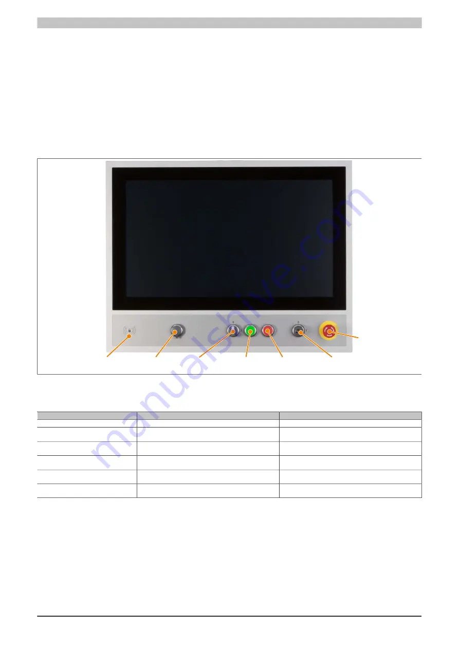
Devices with operating elements come equipped with the following interfaces, buttons and switches on the front:
•
RFID read/write transponder unit
•
USB interface
•
Selector switch (landscape AP99D only)
•
Green and red pushbuttons
•
Key switch
•
E-stop
The button/switch interface is located inside the Panel PC. To access, the interface cover on the back must be
"Removing the interface cover" on page 134
RFID transponder
read/write unit
Front USB
Selector switch Green pushbutton Red pushbutton Key switch
E-stop
Figure 16: Display unit with operating elements (AP99D) - Front view
2.5.1 Button/Switching element
Button / Switch / Transponder
Element
Used switching element
RFID transponderread/write unit
"RFID read/write transponder unit" on page 247
-
Selector switch
"Selector switch RAFIX 22 FS+, 1.30.272.102/2200" on
"Switching element RAFIX 22 FS universal,
1.20.126.005/0000" on page 249
Green pushbutton
"Pushbutton RAFIX 22 FS+, 1.30.270.021/2500" on page
"Switching element RAFIX 22 FS universal,
1.20.126.005/0000" on page 249
Red pushbutton
"Pushbutton RAFIX 22 FS+, 1.30.270.021/2300" on page
"Switching element RAFIX 22 FS universal,
1.20.126.005/0000" on page 249
Key switch
"Key switch RAFIX 22 FS+, 1.30.255.222/0000" on page
"Switching element RAFIX 22 FS universal,
1.20.126.005/0000" on page 249
Emergency stop
"Emergency stop RAFIX 22 FS+ "Plus 1",
1.30.273.502/0300" on page 248
"Switching element RAFIX 22 FS+ PCB gold,
1.20.126.414/0000" on page 249
2.5.1.1 Button, switch and LED configuration
Each button and LED can be individually configured and adapted directly to the application. Various B&R tools
are available for this:
•
B&R Key Editor, B&R KCF Editor or B&R Control Center for Windows operating systems
•
Visual Components for Automation Runtime
Buttons and LEDs from each display unit are processed by the matrix controller in a bit string of 128 bits each.
The positions of buttons and LEDs in the matrix are shown as hardware numbers. These hardware numbers can
be read directly from the target system using the B&R Key Editor, B&R KCF Editor or B&R Control Center.


