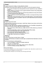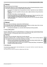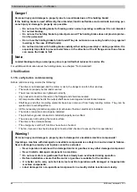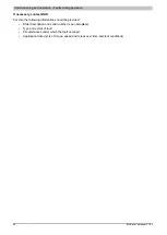
Installation and connection • Connecting and disconnecting the motor
Chapter 5 Installation
and connection
8JSA user's manual V1.00
83
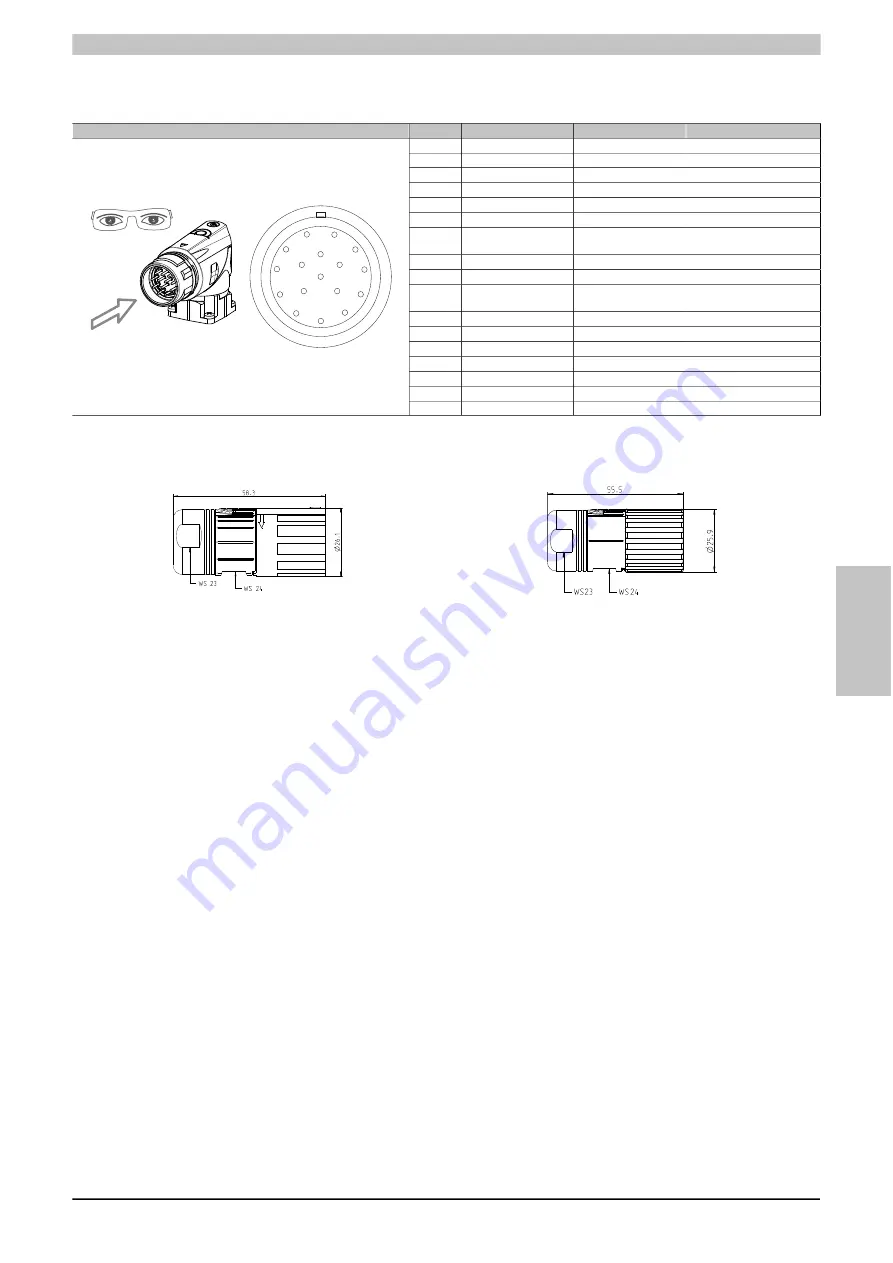
5.4.2.2 EnDat connection - Pinout
EnDat 2.1
Pin
Color
Description
Function
1
Blue
Sense +5 V
Sense 5 V
2
---
---
---
3
---
---
---
4
White
Sense COM
Sense output 0 V
5
---
---
---
6
---
---
---
7
Brown/Green
+5 V output / 0.25A
Encoder power 5
V
8
Violet
T
Clock input
9
Yellow
T\
Clock input inverted
10
White/Green
COM (1, 3-9, 11,
13-15)
0 V encoder power supply
11
---
---
---
12
Blue/Black
B
Channel B
13
Red/Black
B\
Channel B inverted
14
Gray
D
Data output
15
Green/Black
A
Channel A
16
Yellow/Black
A\
Channel A inverted
10
11
8
1
16 17 13
7 15
3
5
6
2
4
14
9
12
17
Pink
D\
Data inverted
5.4.2.3 Encoder connector dimensions
EnDat 2.1 / Resolver (speedtec)
EnDat 2.1 / Resolver (screw connection)


