Technical data
Automation Panel 5000 User's manual V2.11
65
4.1.6.4 Button/Switch interface
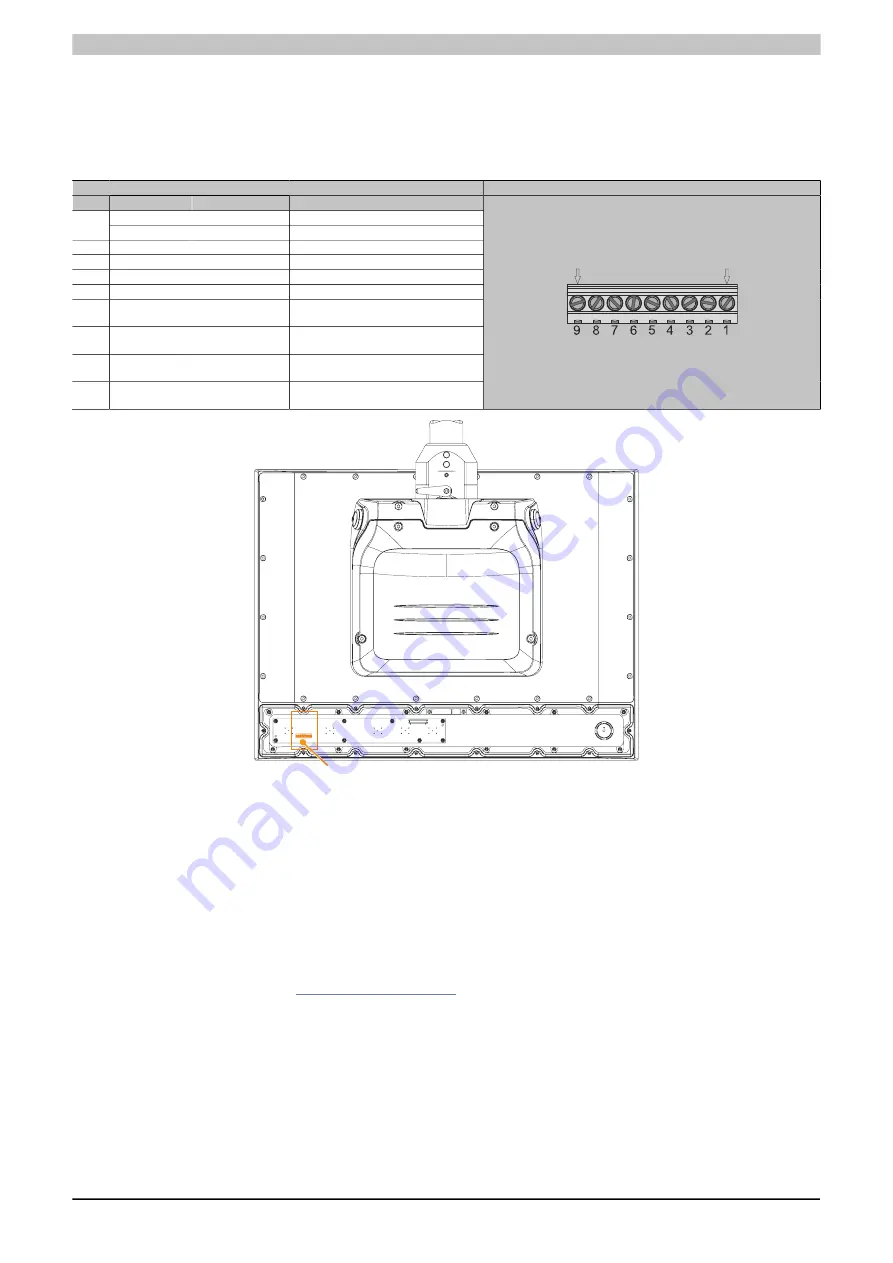
The button/switch interface can be used to externally wire button and switching elements. It is located inside the
panel on the expansion unit. To access, the cover on the back for the expansion option must be removed first
(see
"Installing the expansion unit/cover" on page 163
). Button and switching elements are wired using the 9-
pin terminal strip and a screwdriver.
Description
Figure
Pin
Description
Button/Switch
Contact
T_Select
Selector switch
(normally open contact)
1
T_Blue
Blue pushbutton
(normally open contact)
2
T_Green
Green pushbutton
(normally open contact)
3
T_Red
Red pushbutton
(normally open contact)
4
T_Key
Key switch
(normally open contact)
5
V_Button
Reference potential for pins 1-4
6
NH22
Emergency stop
Normally closed contact
pair 1 emergency stop
7
NH21
Emergency stop
Normally closed contact
pair 1 emergency stop
8
NH12
Emergency stop
Normally closed contact
pair 2 emergency stop
9
NH11
Emergency stop
Normally closed contact
pair 2 emergency stop
Button/Switch interface
9
1
4.1.6.5 B&R wireless assembly
B&R wireless assembly RFM-2-NF of 5ACCKP03.xxxx-000 or 5ACCK05.xxxx-000 expansion units consists of the
following wireless module:
•
SRD (RFID/NFC) module TWN4 MultiTech Nano from Elatec with circuit board antenna from B&R.
The B&R wireless assembly must be connected internally to the system using the USB 2.0 cable.
4.1.6.5.1 Drivers, software and documentation
Drivers, software tools and documentation for approved operating systems are available for download in the Down-
loads section of the B&R website (
). The software packages for the TWN4 MultiTech Nano
must be used.


