Maintenance / Servicing • Mounting the side cover
Section 7
Ma
inte
nanc
e /
Servic
ing
531
Automation PC 620 with 945GME N270 CPU board User's Manual V 1.10
5. Mounting the side cover
The number of Torx (T10) screws varies depending on the system (1, 2, 3 or 5 PCl slots).
5.1 APC620 with 1 PCI slot
•
Disconnect the power supply to the Automation PC 620.
•
Touch the housing or ground connection (not the power supply!) in order to discharge any
electrostatic charge from your body.
•
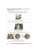
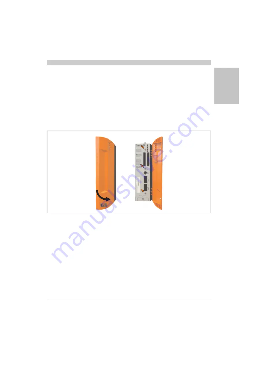
Open the orange front cover. Behind the cover there are 3 Torx screws (T10) that must
be removed.
•
After the screws have been removed, the side cover can be removed by sliding it toward
the front.
Figure 313: Mounting the side cover - APC620, 1 PCI slot
Summary of Contents for Automation PC 620
Page 2: ...2 Automation PC 620 with 945GME N270 CPU board User s Manual V 1 10 ...
Page 4: ...4 Automation PC 620 with 945GME N270 CPU board User s Manual V 1 10 ...
Page 6: ...6 Automation PC 620 with 945GME N270 CPU board User s Manual V 1 10 ...
Page 568: ...568 Appendix A Glossary Automation PC 620 with 945GME N270 CPU board User s Manual V 1 10 ...


