9
Automation PC 620 with 945GME N270 CPU board User's Manual V 1.10
Table of contents
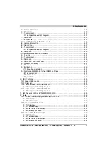
2.10.1 Supply voltage for the 5PC600.SX05-00 (revision >= H0) and 5PC600.SX05-01
(revision >= H0) ............................................................................................................... 91
2.10.2 Power calculation with system unit 5PC600.SX05-00 (revision >= H0) ................ 93
2.10.3 Power calculation with system unit 5PC600.SX05-01 (revision >= H0) ................ 94
2.10.4 Supply voltage for the 5PC600.SX05-00 (revision < H0) and 5PC600.SX05-01
(revision <= H0) ............................................................................................................... 95
2.10.5 Power calculation with system unit 5PC600.SX05-05 revision < H0 .................... 97
2.10.6 Power calculation with system unit 5PC600.SX05-01 revision < H0 .................... 99
2.11 Power management for the APC620 embedded system unit ................................... 100
2.11.1 Supply voltage for the 5PC600.SE00-00, 5PC600.SE00-01 and 5PC600.SE00-02 .
100
2.12 Humidity specifications .............................................................................................. 101
2.13 Device interfaces ...................................................................................................... 102
2.13.1 Serial interface COM1 ......................................................................................... 104
2.13.2 Serial interface COM2 ......................................................................................... 105
2.13.3 X2X (only APC620 embedded) ........................................................................... 106
2.13.4 CAN (only APC620 embedded) .......................................................................... 106
2.13.5 CAN node number (only APC620 embedded) .................................................... 107
2.13.6 CAN terminating switch / LED (only APC620 embedded) .................................. 107
2.13.7 Status LEDs CAN / X2X (only APC620 embedded) ........................................... 108
2.13.8 POWERLINK (only APC620 embedded) ............................................................ 108
2.13.9 POWERLINK station number (only APC620 embedded) ................................... 110
2.13.10 Ethernet connection ETH (only APC620 embedded) ....................................... 110
2.13.11 Ethernet connection ETH1 ................................................................................ 111
2.13.12 Ethernet connection ETH2 ................................................................................ 113
2.13.13 USB port ........................................................................................................... 114
2.13.14 USB connection (only APC620 embedded) ...................................................... 115
2.13.15 +24 VDC supply voltage ................................................................................... 116
2.13.16 Monitor / Panel connection ............................................................................... 119
2.13.17 MIC, Line IN and Line OUT ports ...................................................................... 125
2.13.18 Add-on interface slot ......................................................................................... 126
2.13.19 Add-on UPS module slot ................................................................................... 127
2.13.20 AP Link Slot ...................................................................................................... 128
2.13.21 PCI slots ............................................................................................................ 128
2.13.22 Status LEDs ...................................................................................................... 131
2.13.23 Status LEDs Power, CF, Link (only APC620 embedded) ................................. 132
2.13.24 CompactFlash slot (CF1) .................................................................................. 133
2.13.25 Hard disk / CompactFlash slot (HDD/CF2) ....................................................... 134
2.13.26 CompactFlash slots (only APC620 embedded) ................................................ 136
2.13.27 Power button ..................................................................................................... 137
2.13.28 Reset button ...................................................................................................... 137
2.13.29 PS/2 keyboard/mouse ....................................................................................... 138
2.13.30 Battery ............................................................................................................... 139
2.13.31 Hardware Security Key ..................................................................................... 141
2.13.32 Slide-in slot 1 drive slot ..................................................................................... 142
2.13.33 Slide-in slot 2 drive slot ..................................................................................... 143
Summary of Contents for Automation PC 620
Page 2: ...2 Automation PC 620 with 945GME N270 CPU board User s Manual V 1 10 ...
Page 4: ...4 Automation PC 620 with 945GME N270 CPU board User s Manual V 1 10 ...
Page 6: ...6 Automation PC 620 with 945GME N270 CPU board User s Manual V 1 10 ...
Page 568: ...568 Appendix A Glossary Automation PC 620 with 945GME N270 CPU board User s Manual V 1 10 ...


