Commissioning • Connection examples
186
Automation PC 810 with GM45 CPU board user's manual V1.28
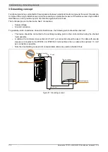
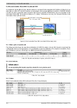
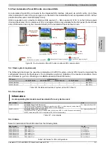
5.5 One AP900 and one AP800 via onboard SDL
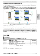
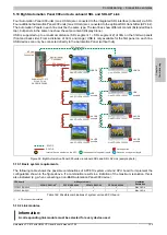
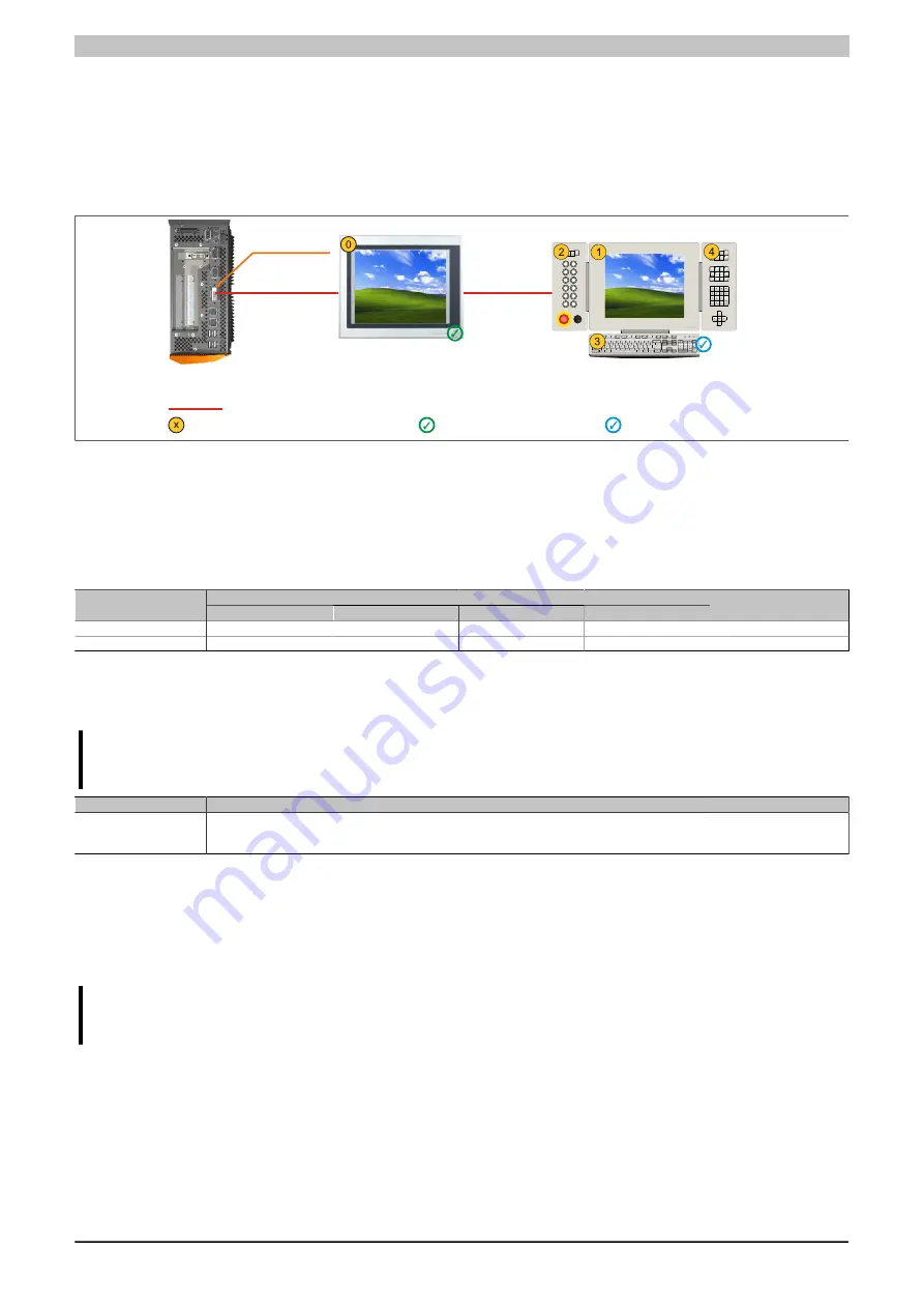
An Automation Panel 900 and an Automation Panel 800 are connected to the integrated SDL interface (onboard)
via SDL.
USB is supported up to a maximum distance (segment 1 + segment 2) of 30 m on the two displays. Starting at a
distance of 30 m, USB is only available on the first display (front and back) up to a maximum of 40 m. USB devices
can only be connected directly to the Automation Panel 900 or extension keyboard (without a hub).
USB OK
Automation PC 810
SDL Segment 1
Max. 40 m
Link: 5DLSDL.1000-01
SDL Segment 2
Max. 40 m
Automation Panel 800
USB
possible
Monitor / Panel
Connection
SDVO-B
Internal device number on the APC
Independent of segment length
Depends on segment length
Figure 87: One AP900 and one AP800 via onboard SDL (sample photo)
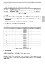
5.5.1 Basic system requirements
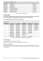
The following table shows the possible combinations of APC810 system unit and CPU board to implement the
configuration shown in the figure above. If a combination results in a limitation of the maximum resolution, this is
also indicated (e.g. when connecting a non-B&R Automation Panel 900 device).
with system unit
CPU board
5PC810.SX01-00
5PC810.SX02-00
5PC810.SX03-00
5PC810.SX05-00
Limitation
Resolution
5PC800.BM45-00
✓
✓
✓
✓
Max. UXGA
5PC800.BM45-01
✓
✓
✓
✓
Max. UXGA
Table 144: Possible combinations of system unit and CPU board
5.5.2 Link modules
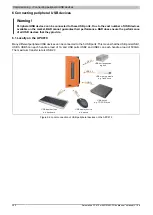
Information:
A corresponding link module must be selected for every device used.
Model number
Description
Note
5DLSDL.1000-01
Automation Panel Link SDL transceiver
Connections for SDL in, transfer of display data, touch screen, USB 1.1, matrix keys, and service data,
24 VDC (screw clamp 0TB103.9 or cage clamp 0TB103.91 sold separately).
For Automation Panel 900
Table 145: Link modules
5.5.3 Cables
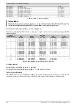
For a selection of SDL cables for connecting the AP900 display to the AP900 display, see see "Cables" on page 182.
For a selection of SDL cables for connecting the AP800 display to the AP900 display, see see "Cables" on page 184.
Information:
Detailed technical data about the cables can be found in chapter "Accessories".
5.5.4 BIOS settings
No special BIOS settings are necessary for operation.
For detailed information, see the user's manual for the B&R industrial PC used.
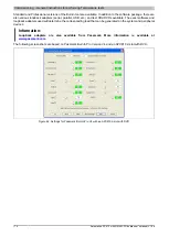
Touch screen functionality
The COM C must be enabled in BIOS in order to operate the connected panel touch screen on the monitor / panel
connection (found in the BIOS menu under "Advanced - Main board / Panel Features - Legacy Devices").


