Technical data • Complete system
Chapter 2
Technical data
Automation Panel 9x3 User's Manual V1.00
21
2.3 Environmental characteristics
2.3.1 Temperature specifications
Display units and link modules can be combined. The many different configurations possible result in varying
maximum ambient temperatures, which can be seen in the following table in this section.
Information:
The maximum specified ambient temperatures for operation were determined under worst-case condi-
tions. Experience has shown that higher ambient temperatures can be reached in typical applications,
e.g. those in Microsoft Windows. Testing and evaluation must be performed on-site by the user (tem-
peratures can be read in BIOS or with the B&R Control Center).
Information regarding worst-case conditions
•
BurnInTest tool (BurnInTest V4.0 Pro from Passmark Software) for simulating a 100% load on the interface
via loop back adapters (serial interface, USB interfaces)
•
Maximum system expansion and power consumption
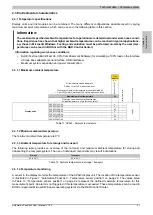
2.3.1.1 Maximum ambient temperature
Link
module
SDL / DVI
All temperature values in degrees
Celsius (°C) at 500 m above sea level.
The maximum ambient temperature is typically derated by
1°C per 1000 meters (starting at 500 meters above sea level).
5DLSDL.1001-00
Maximum ambient temperature
55
What else can also be operated at the max.
ambient temperature, or are there any limits?
Temperature limits
Location of sensor(s)
5AP923.1215-00
✓
-
5AP923.1505-00
✓
-
5AP923.1906-00
45
-
5AP933.156B-00
✓
-
5AP933.185B-00
✓
-
5AP933.215C-00
45
-
Display units
5AP933.240C-00
45
-
Display
Table 11: AP9x3 - Ambient temperature
2.3.1.2 Minimum ambient temperature
The minimum ambient temperature is 0°C.
2.3.1.3 Ambient temperature for storage and transport
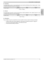
The following table provides an overview of the minimum and maximum ambient temperature for storing and
transporting the complete system. The use of individual components may result in limitations.
Storage
Transport
-20 to 60°C
-20 to 60°C
Table 12: Ambient temperature in storage / transport
2.3.1.4 Temperature monitoring
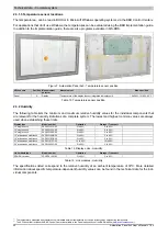
A sensor in the display monitors the temperature of the AP9x3 display unit. The location of the temperature sensor
is illustrated in Figure 7 "Automation Panel 9x3 - Temperature sensor position" on page 22. The values listed
in Table 13 "Temperature sensor position" on page 22 represent the defined maximum temperature for this
measurement point. An alarm is not triggered if this temperature is exceeded. These temperatures can be read in
BIOS or approved Microsoft Windows operating systems via the B&R Control Center.


