Installation • Installation
Chapter 3 Installation
Automation Panel 9x3 User's Manual V1.00
47
Chapter 3 • Installation
1 Installation
Danger!
•
All supply voltage must be disconnected before removing device covers or components or
removing/installing accessories, hardware or cables.
•
The power cable must be disconnected from the device and from the voltage supply.
•
Before the device can be connected to the power supply and turned on, all covers, components,
accessories, hardware and cables must be installed or attached.
1.1 Mounting an Automation Panel 9x3
The Automation Panel 9x3 is mounted in the cutout using retaining clips. The number of retaining clips depends
on the display unit.
Installation notes
•
Environmental conditions must be taken into consideration.
•
When installed in an enclosed housing, enough space must be available for air to circulate sufficiently.
•
This device must be mounted to a flat, clean and burr-free surface.
•
This device is only certified for operation in closed rooms.
•
This device must not be subjected to direct sunlight.
•
Ventilation holes must not be covered.
•
This device must be mounted in one of the approved orientations.
•
The wall or control cabinet must be able to withstand four times the total weight of the device.
•
The flex radius of connected cables (DVI, SDL, USB, etc.) must not be exceeded.
•
This device must be mounted in a position that minimizes glare on the screen.
•
This device must be mounted in a position and orientation that make viewing as easy as possible for the
operator.
The thickness of the wall or cabinet plate must be between 1 mm and 6 mm.
A hex-head screwdriver is needed to tighten and loosen the screws on the retaining clips. The maximum torque
for the retaining clips is 1 Nm.
Devices must be installed on flat, clean and burr-free surface; uneven areas can cause damage to the display
when the screws are tightened or intrusion of dust and water.
Procedure
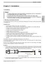
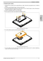
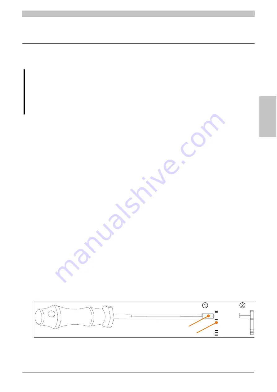
1. Check whether the included mounting screws are screwed into the retaining clips. If not, then the mounting
screws must be screwed into the retaining clips with a hex-head screwdriver. The mounting screws must only
be screwed in far enough that they no longer protrude above the retaining clip.
Retaining clips
Mounting screws
Figure 26: Prepare retaining clips
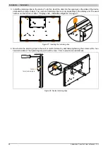
2. Insert the device into the front side of the smooth, flat installation cutout. The dimensions for the cutout can

