background image

Technical data  • Complete system

16

Automation Panel 9x3 User's Manual V1.00

2.2 Mechanical characteristics

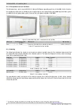
2.2.1 Dimensions

B

A

K

E

J

G

H

F

C

D

I

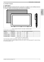
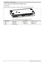
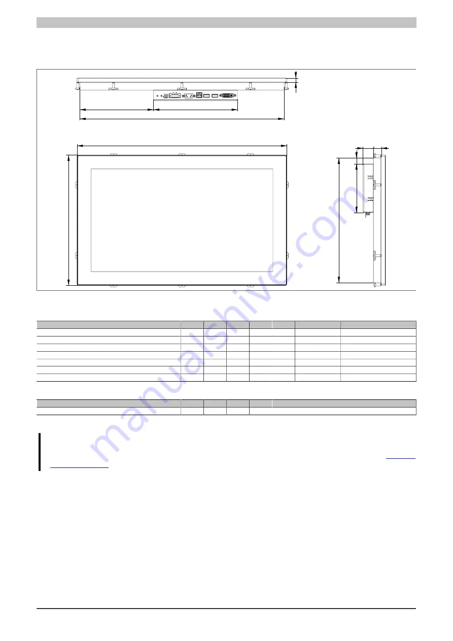
Figure 3: Automation Panel 9x3 + link module - Dimensions

All dimensions are specified in mm.

Display type

Model number

A

B

C

D

E

F

G

12" single-touch

5AP923.1215-00

315

239

302

48

9

226

13.5

15" single-touch

5AP923.1505-00

370

288

357

84.5

9

275

14.5

19" single-touch

5AP923.1906-00

440

358

427

149

9

345

23

15" widescreen multi-touch

5AP933.156B-00

414

258.5

401

105.5

9

245.5

20

18" widescreen multi-touch

5AP933.185B-00

475

295

462

166.5

9

282

18

21" widescreen multi-touch

5AP933.215C-00

541.5

333

528.5

199.75 9

320

18

24" widescreen multi-touch

5AP933.240C-00

598.5

364

585.5

228.25 9

351

18

Table 5: Display unit - Dimensions

Link module type

Model number

H

I

J

K

SDL/DVI receiver

5DLSDL.1001-00

23.6

13.5

110

190

Table 6: Link modules - Dimensions

Information:

3D  diagrams  are  available  upon  request  or  can  be  downloaded  from  the  B&R  website 

www.br-

automation.com

.

Summary of Contents for MAAP9x3-ENG

Page 1: ...date of publication however Bernecker Rainer Industrie Elektronik Ges m b H makes no warranty ex pressed or implied with regard to the products or documentation contained within this manual In additi...

Page 2: ...2 Chapter 1 General information Chapter 2 Technical data Chapter 3 Installation Chapter 4 Standards and certifications Chapter 5 Accessories Chapter 6 Maintenance and service Appendix A...

Page 3: ...escription of individual modules 12 1 2 1 Display units 12 1 2 2 Link modules 12 1 3 Structure Configuration 13 1 3 1 Configuration 13 2 Complete system 14 2 1 Connection options 14 2 1 1 SDL operatin...

Page 4: ...4 5 Touch screen calibration 55 5 1 Single touch analog resistive 55 5 1 1 Windows 7 Professional Ultimate 55 5 1 2 Windows Embedded Standard 7 Embedded Premium 55 5 1 3 Windows XP Professional 55 5 1...

Page 5: ...flex cables with extender 75 3 5 1 5CASDL 0xx0 13 75 3 6 USB cables 79 3 6 1 5CAUSB 00xx 00 79 3 7 RS232 cables 80 3 7 1 9A0014 xx 80 Chapter 6 Maintenance and service 82 1 Cleaning 82 2 Tips for ext...

Page 6: ...General information Manual history 6 Automation Panel 9x3 User s Manual V1 00 Chapter 1 General information 1 Manual history Version Date Change 1 00 10 Dec 13 First version Table 1 Manual history...

Page 7: ...es for proper ESD handling Electrical components with a housing Do not touch the connector contacts on connected cables Do not touch the contact tips on circuit boards Electrical components without a...

Page 8: ...ng monitoring devices or uninterruptible power supplies it is necessary for certain parts to carry dangerous voltage levels over 42 VDC Touching one of these parts can result in a life threatening ele...

Page 9: ...Separation of materials It is necessary to separate different materials so the device can undergo an environmentally friendly recycling process Component Disposal Programmable logic controllers Operat...

Page 10: ...ent Caution Disregarding these safety guidelines and notices can result in injury or damage to equipment Information This information is important for preventing errors Table 3 Description of the safe...

Page 11: ...30 m 75 5CASDL 0400 13 SDL flex cable with extender 40 m 75 5CASDL 0430 13 SDL flex cable with extender 43 m 75 Terminal blocks 0TB103 9 Connector 24 VDC 3 pin female 3 31 mm screw clamp protected ag...

Page 12: ...een and form the basis for each Automation Panel 9x3 and Panel PC 900 System Different display sizes and touch screen technologies are available These display units can be operated exclusively as a co...

Page 13: ...essential for operation as an Automation Panel 9x3 Display unit Link module Display unit Configuration Base system Select 1 5DLSDL 1001 00 SDL DVI receiver Link module Select 1 Select 1 Terminal block...

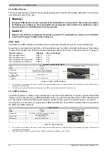
Page 14: ...aces on the Automation Panel 9x3 9xD Panel In interface USB In x Supply voltage Brightness controls x USB1 USB2 USB 1 1 COM touch interface x Grounding Maximum cable length 40 m 2 1 1 2 SDL Operating...

Page 15: ...Industrial PC Supply voltage Grounding Supply voltage Grounding Availability of interfaces on the Automation Panel 923 92D Panel In interface USB In USB 2 0 Supply voltage Brightness controls USB1 US...

Page 16: ...touch 5AP923 1906 00 440 358 427 149 9 345 23 15 widescreen multi touch 5AP933 156B 00 414 258 5 401 105 5 9 245 5 20 18 widescreen multi touch 5AP933 185B 00 475 295 462 166 5 9 282 18 21 widescreen...

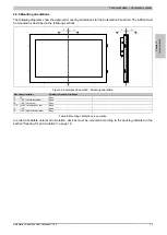
Page 17: ...aining clips 12 single touch 5AP923 1215 00 304 228 1 6 10 pcs 15 single touch 5AP923 1505 00 359 277 1 6 10 pcs 19 single touch 5AP923 1906 00 429 347 1 6 12 pcs 15 widescreen multi touch 5AP933 156B...

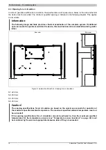
Page 18: ...intain the device this must be taken into consideration during instal lation Rear view Side view S1 S1 S4 S2 S2 S3 S3 Figure 5 Automation Panel 9x3 Spacing for air circulation S1 20 mm S2 50 mm S3 50...

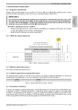
Page 19: ...e following sections C D A B 0 0 Figure 6 Automation Panel 9x3 Mounting orientation Mounting orientation Ambient temperature limitation 0 0 None A 90 counterclockwise None B 90 clockwise None C D 180...

Page 20: ...15 00 2200 15 single touch 5AP923 1505 00 3700 19 single touch 5AP923 1906 00 5800 15 widescreen multi touch 5AP933 156B 00 3850 18 widescreen multi touch 5AP933 185B 00 4850 21 widescreen multi touch...

Page 21: ...C per 1000 meters starting at 500 meters above sea level 5DLSDL 1001 00 Maximum ambient temperature 55 What else can also be operated at the max ambient temperature or are there any limits Temperature...

Page 22: ...en establishing these limits Display type Model number Operation Storage Transport 12 single touch 5AP923 1215 00 5 to 90 5 to 90 15 single touch 5AP923 1505 00 8 to 90 8 to 90 19 single touch 5AP923...

Page 23: ...on 2 3 4 Shock The following table provides an overview of the maximum shock specifications of the complete system The use of individual components may result in limitations Operation Storage Transpor...

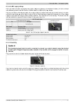
Page 24: ...C supply voltage Table 18 24 VDC supply voltage connection Electrical characteristics Nominal voltage 24 VDC 25 Nominal current Max 2 5 A Electrical isolation Yes Uninterruptible power supply No 2 4 2...

Page 25: ...ck diagram shows the simplified structure of the 5DLSDL 1001 00 SDL DVI receiver link module for the Automation Panel 9x3 USB Type B USB Type A USB Type A Display data IN switches Panel Link receiver...

Page 26: ...Automation Panel 9x3 1 2 3 4 5 6 7 8 9 Figure 9 Overview of interfaces Link module SDL DVI Receiver No Type of interface No Type of interface 1 Panel In SDL DVI Panel In interface 6 24 VDC power 24 VD...

Page 27: ...olarity Pin Description 1 2 Functional ground 3 Model number Short description Terminal blocks 0TB103 9 Connector 24 V 5 08 3 pin screw clamp 0TB103 91 Connector 24 V 5 08 3 pin cage clamp 3 pin femal...

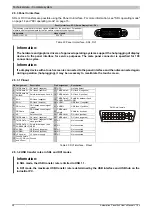
Page 28: ...Hot plug detect 2 TMDS data 2 DVI lane 2 positive 17 TMDS data 0 DVI lane 0 negative 3 TMDS data 2 4 SHIELD Shield for data pair 2 and 4 18 TMDS data 0 DVI lane 0 positive 4 SDL SDL lane negative 19...

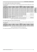
Page 29: ...L 0100 00 5CASDL 0100 01 5CASDL 0100 03 15 5CASDL 0150 00 5CASDL 0150 01 5CASDL 0150 03 5CASDL 0150 00 5CASDL 0150 01 5CASDL 0150 03 5CASDL 0150 00 5CASDL 0150 01 5CASDL 0150 03 5CASDL 0150 00 5CASDL...

Page 30: ...12 Mbit s high speed 480 Mbit s Current load2 USB1 USB2 A total of max 1 A Cable length USB 2 0 Max 5 m without hub 2x USB type A female USB2 USB1 Table 26 USB1 USB2 interfaces 1 The interfaces etc av...

Page 31: ...FO Transfer rate Max 9600 baud Bus length Max 5 m Pin Assignment 1 NC 2 RXD 3 TXD 4 NC 5 GND 6 NC 7 RTS 8 CTS 9 NC 9 pin male DSUB connector 5 1 9 6 Table 28 COM Pinout 1 The interfaces etc available...

Page 32: ...al 12 1 Colors 16 2 million Resolution XGA 1024 x 768 pixels Contrast 700 1 Viewing angles Horizontal Direction R Direction L 80 Vertical Direction U Direction D 80 Backlight Classification LED Bright...

Page 33: ...tion Panel 9x3 User s Manual V1 00 33 3 1 1 4 Dimensions 315 239 Figure 12 5AP23 1215 00 Dimensions 3 1 1 5 Temperature humidity diagram Temperature C Operation Storage Transport Relative humidity RH...

Page 34: ...lors 16 2 million Resolution XGA 1024 x 768 pixels Contrast 700 1 Viewing angles Horizontal Direction R Direction L 80 Vertical Direction U Direction D 70 Backlight Classification LED Brightness 350 c...

Page 35: ...70 288 Figure 14 5AP23 1505 00 Dimensions 3 1 2 5 Temperature humidity diagram 0 0 10 20 30 40 50 60 70 80 90 80 70 60 50 40 30 20 10 5 10 100 95 90 85 80 75 70 65 60 55 50 45 40 35 30 25 20 15 Temper...

Page 36: ...lors 16 7 million Resolution SXGA 1280 x 1024 pixels Contrast 2000 1 Viewing angles Horizontal Direction R Direction L 89 Vertical Direction U Direction D 89 Backlight Classification LED Brightness 30...

Page 37: ...40 358 Figure 16 5AP23 1906 00 Dimensions 3 1 3 5 Temperature humidity diagram 0 0 10 20 30 40 50 60 70 80 90 80 70 60 50 40 30 20 10 5 10 100 95 90 85 80 75 70 65 60 55 50 45 40 35 30 25 20 15 Temper...

Page 38: ...s 16 7 million Resolution HD 1366 x 768 pixels Contrast 500 1 Viewing angles Horizontal Direction R Direction L 85 Vertical Direction U Direction D 80 Backlight Classification LED Brightness 300 cd m...

Page 39: ...4 258 5 Figure 18 5AP933 156B 00 Dimensions 3 1 4 5 Temperature humidity diagram 0 0 10 20 30 40 50 60 70 80 90 80 70 60 50 40 30 20 10 5 10 100 95 90 85 80 75 70 65 60 55 50 45 40 35 30 25 20 15 Temp...

Page 40: ...16 7 million Resolution HD 1366 x 768 pixels Contrast 1000 1 Viewing angles Horizontal Direction R Direction L 170 Vertical Direction U Direction D 160 Backlight Classification LED Brightness 300 cd...

Page 41: ...95 475 Figure 20 5AP933 185B 00 Dimensions 3 1 5 5 Temperature humidity diagram 0 0 10 20 30 40 50 60 70 80 90 80 70 60 50 40 30 20 10 5 10 100 95 90 85 80 75 70 65 60 55 50 45 40 35 30 25 20 15 Tempe...

Page 42: ...rs 16 7 million Resolution FHD 1920 x 1080 pixels Contrast 1000 1 Viewing angles Horizontal Direction R Direction L 178 Vertical Direction U Direction D 178 Backlight Classification LED Brightness 250...

Page 43: ...1 5 333 Figure 22 5AP933 215C 00 Dimensions 3 1 6 5 Temperature humidity diagram 0 0 10 20 30 40 50 60 70 80 90 80 70 60 50 40 30 20 10 5 10 100 95 90 85 80 75 70 65 60 55 50 45 40 35 30 25 20 15 Temp...

Page 44: ...6 7 million Resolution FHD 1920 x 1080 pixels Contrast 5000 1 Viewing angles Horizontal Direction R Direction L 89 Vertical Direction U Direction D 89 Backlight Classification LED Brightness 300 cd m...

Page 45: ...8 5 364 Figure 24 5AP933 240C 00 Dimensions 3 1 7 5 Temperature humidity diagram 0 0 10 20 30 40 50 60 70 80 90 80 70 60 50 40 30 20 10 5 10 100 95 90 85 80 75 70 65 60 55 50 45 40 35 30 25 20 15 Temp...

Page 46: ...tness button Yes 1 Interfaces COM1 Type RS232 modem capable not electrically isolated Design 9 pin male DSUB connector Max baud rate 9 6 kbit s USB Quantity 3 2x Type A 1x Type B Type USB 2 0 Design 2...

Page 47: ...n one of the approved orientations The wall or control cabinet must be able to withstand four times the total weight of the device The flex radius of connected cables DVI SDL USB etc must not be excee...

Page 48: ...clips may vary depending on the display unit The exact number can be found in Table 7 Display units Installation diagrams on page 17 Figure 27 Inserting the retaining clips 4 Now fasten the retaining...

Page 49: ...anel from the control cabinet To do so follow the steps in section Mounting an Automation Panel 9x3 on page 47 in reverse order 4 Place the Automation Panel on a clean flat surface 5 Remove the Torx s...

Page 50: ...ion of 0 75 mm2 to 1 5 mm2 and wire end sleeves are to be used Installing the 0TB103 9 screw clamp terminal block Insert the wires with the wire end sleeves into the terminal contacts as shown in the...

Page 51: ...ted Before connecting the mains cable it is important to make absolutely sure that it has been disconnected from the power source e g power supply 1 Touch the housing or ground connection in order to...

Page 52: ...arantee safe conductance of electric disturbances the following points should be observed The device should be connected to the central grounding point in the control cabinet using the shortest route...

Page 53: ...nstalling or connecting cables Information The maximum torque for the locating screws is 0 5 Nm Flex radius Locating screw Locating screw Figure 35 Flex radius Cable connection Information The specifi...

Page 54: ...st be put into operation first before additional hardware is installed Caution Before the device is put into operation it must first be acclimated to room temperature It should not be immediately subj...

Page 55: ...edded Standard 7 setup or if a an Automation Panel 800 900 9x3 has been connected after setup The necessary driver is available in the Downloads section of the B R website www br automation com 5 1 3...

Page 56: ...b 3 Select the Automation Panel from the list 4 Set the desired brightness using the slider control Figure 36 Adjusting the display brightness Information Changes to these settings are displayed onlin...

Page 57: ...as EN 61131 2 2007 Programmable logic controllers Part 2 Equipment requirements and tests EN 61000 6 2 2005 Electromagnetic compatibility EMC Part 6 2 Generic standards Immunity for industrial environ...

Page 58: ...ds from organi zations such as ISO IEC and CENELEC as well as national standards from organizations such as UL CSA FCC VDE VE etc We are committed to ensuring the reliability of our products in an ind...

Page 59: ...lamp pro tected against vibration by the screw flange 0TB103 91 Connector 24 VDC 3 pin female 3 31 mm cage clamp pro tected against vibration by the screw flange Table 45 0TB103 9 0TB103 91 Order data...

Page 60: ...tage 300 V Nominal current 2 10 A contact Contact resistance 5 m Table 46 0TB103 9 0TB103 91 Technical data 1 Yes although applies only if all components installed within the complete system have this...

Page 61: ...ost cases if the fdisk mbr command is additionally executed on the USB flash drive 2 1 2 Order data Model number Short description Figure USB accessories 5MMUSB 2048 01 USB 2 0 flash drive 2048 MB B R...

Page 62: ...eak Shock Operation Max 1500 g peak Storage Max 1500 g peak Transport Max 1500 g peak Altitude Operation Max 3048 m Storage Max 12192 m Transport Max 12192 m Mechanical characteristics Dimensions Widt...

Page 63: ...GL Yes 1 Cable structure Wire cross section AWG 28 Shielding Individual cable pairs and entire cable Cable shielding Tinned copper mesh optical coverage 86 Outer sheathing Material PVC Color Beige La...

Page 64: ...1 1 4 Flex radius specifications Male connector Ferrite Ferrite Ferrite Flex radius Connector Ferrite bead Flex radius Ferrite bead Ferrite bead Figure 39 Flex radius specifications 3 1 1 5 Dimension...

Page 65: ...le cable yourself it should be wired according to these specifications If a self built cable is used B R cannot guarantee that it will function properly All cables provided by B R are guaranteed to fu...

Page 66: ...Individual cable pairs and entire cable Cable shielding Tinned copper mesh optical coverage 85 Outer sheathing Material PVC Color Black Labeling E74020 C UL AWM STYLE 20176 80 C 30V VW 1 DVI DIGITAL L...

Page 67: ...1 00 67 3 2 1 4 Flex radius specifications Male connector Ferrite Ferrite Ferrite Flex radius Connector Ferrite bead Flex radius Ferrite bead Ferrite bead Figure 42 Flex radius specifications 3 2 1 5...

Page 68: ...e yourself it should be wired according to these specifications If a self built cable is used B R cannot guarantee that it will function properly All cables provided by B R are guaranteed to function...

Page 69: ...cture Wire cross section AWG 28 AWG 24 Shielding Individual cable pairs and entire cable Cable shielding Tinned copper mesh optical coverage 85 Outer sheathing Material PVC Color Black Connector Type...

Page 70: ...1 4 Flex radius specifications Male connector Ferrite Ferrite Ferrite Flex radius Connector Ferrite bead Flex radius Ferrite bead Ferrite bead Figure 45 Flex radius specifications 3 3 1 5 Dimensions...

Page 71: ...itable cable yourself it should be wired according to these specifications If a self built cable is used B R cannot guarantee that it will function properly All cables provided by B R are guaranteed t...

Page 72: ...L 0300 03 General information Certification CE Yes cULus Yes GL Yes 1 Cable structure Wire cross section AWG 24 control wires AWG 26 DVI USB data Properties Silicone and halogen free Shielding Individ...

Page 73: ...r ferrite bead ferrite bead tested 300 000 cycles with 15x cable diameter 4800 cycles hour Drag chain data Flex cycles 300 000 Velocity 4800 cycles hour Flex radius 180 mm 15x cable diameter Hub 460 m...

Page 74: ...ions If a self built cable is used B R cannot guarantee that it will function properly All cables provided by B R are guaranteed to function properly Pinout DVI 24 1 male DVI 24 1 male Cable shield Ca...

Page 75: ...control wires AWG 26 DVI USB data Properties Silicone and halogen free Shielding Individual cable pairs and entire cable Cable shielding Aluminum clad foil tinned copper mesh Outer sheathing Material...

Page 76: ...ith 15x cable diameter 4800 cycles hour Drag chain data Flex cycles 300 000 Velocity 4800 cycles hour Flex radius 180 mm 15x cable diameter Hub 460 mm Weight Approx 5430 g Approx 7200 g Approx 7790 g...

Page 77: ...itable cable yourself it should be wired according to these specifications If a self built cable is used B R cannot guarantee that it will function properly All cables provided by B R are guaranteed t...

Page 78: ...flex cables with an extender must be connected between the B R Industrial PC and the Automation Panel display unit in the correct direction The proper signal direction is indicated on the extender B R...

Page 79: ...rmation Certification CE Yes cULus Yes Cable structure Wire cross section AWG 24 28 Shielding Entire cable Outer sheathing Color Beige Connector Type USB type A male and USB type B male Mechanical cha...

Page 80: ...with touch screen 5 m 9A0014 10 RS232 extension cable for remote operation of a display unit with touch screen 10 m Table 62 9A0014 02 9A0014 05 9A0014 10 Order data 3 7 1 3 Technical data Product ID...

Page 81: ...le cable yourself it should be wired according to these specifications If a self built cable is used B R cannot guarantee that it will function properly All cables provided by B R are guaranteed to fu...

Page 82: ...intended functions from being triggered when handling the touch screen or pressing keys This device should be cleaned with a moist cloth The cloth should be moistened with water and detergent a screen...

Page 83: ...the only cause of screen burn in Screen burn in is also referred to as burn in effect image retention memory effect memory sticking or ghost image There are basically two types Area type This type of...

Page 84: ...his stands for a value that has not been defined This may be be cause a cable manufacturer does not provide certain technical data for example NO Normally open A N O relay contact TBD To be defined Us...

Page 85: ...imensions 45 Figure 25 5AP933 240C 00 Temperature humidity diagram 45 Figure 26 Prepare retaining clips 47 Figure 27 Inserting the retaining clips 48 Figure 28 Fasten retaining clips 48 Figure 29 Remo...

Page 86: ...ble 31 5AP923 1505 00 Order data 34 Table 32 5AP923 1505 00 Technical data 34 Table 33 5AP923 1906 00 Order data 36 Table 34 5AP923 1906 00 Technical data 36 Table 35 5AP933 156B 00 Order data 38 Tabl...

Page 87: ...cables Structure 74 Table 58 5CASDL 0300 13 5CASDL 0400 13 5CASDL 0430 13 Order data 75 Table 59 5CASDL 0300 13 5CASDL 0400 13 5CASDL 0430 13 Technical data 75 Table 60 5CAUSB 0018 00 5CAUSB 0050 00 O...

Page 88: ...CASDL 0018 01 69 5CASDL 0018 03 72 5CASDL 0050 00 66 5CASDL 0050 01 69 5CASDL 0050 03 72 5CASDL 0100 00 66 5CASDL 0100 01 69 5CASDL 0100 03 72 5CASDL 0150 00 66 5CASDL 0150 01 69 5CASDL 0150 03 72 5CA...

Page 89: ...ors 22 Vibration 23 Weight specifications 20 B backlight 31 83 brightness 31 Brightness controls 31 C Cable connections 53 Cables 63 DVI cables 63 SDL cables 66 SDL cables with 45 male connector 69 SD...

Page 90: ...functional ground 27 52 G General tolerance 10 ground connection 27 52 Grounding 27 52 Guidelines 10 I immunity to disturbances 52 Installation Link module 49 Installation notes 47 Installing the DC m...

Page 91: ...83 SDL cables 66 SDL cables with 45 male connector 69 SDL flex cables 72 SDL flex cables with extender 75 SDL operating mode 14 Mode 1 14 Mode 2 14 SDL resolution 29 serial interface 31 service life o...

Reviews: