Installation • Key and LED configuration
148
Power Panel 500 user's manual V1.40
6 Key and LED configuration
Each button and LED can be individually configured and adapted directly to the application. Various B&R tools
are available for this:
•
B&R Key Editor for Windows operating systems
•
Visual Components for Automation Runtime
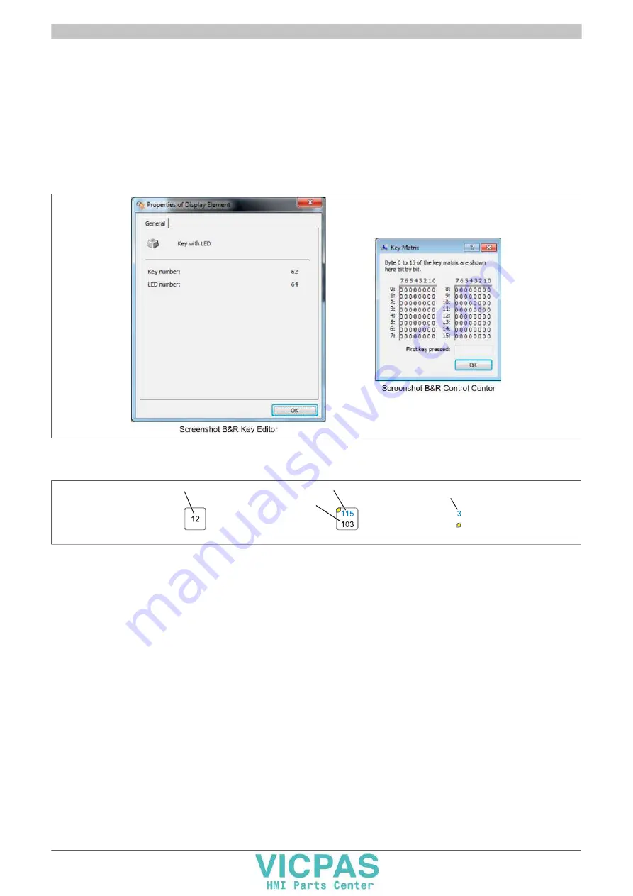
Keys and LEDs from each device are processed by the matrix controller in a bit sequence of 128 bits each.
The positions of keys and LEDs in the matrix are shown as hardware numbers. These hardware numbers can be
read directly from the target system using the B&R Key Editor or B&R Control Center.
Figure 75: Hardware numbers in the B&R Key Editor and B&R Control Center
The images below show the positions of buttons and LEDs in the matrix. This information is indicated as follows.
Key with LED
Hardware number of LED
Hardware number of key
Key without LED
Hardware number of key
Hardware number of LED
LED
Figure 76: Display - Keys and LEDs


