Software • BIOS options
Chapter 4 Software
Power Panel 500 user's manual V1.40
215
1.11.4 Interrupt assignments in APIC mode
A total of 23 IRQs are available in APIC (
A
dvanced
P
rogrammable
I
nterrupt
C
ontroller) mode. Enabling this option
is only effective if done before the operating system is installed.
IRQ
0
1
2
3
4
5
6
7
8
9
10 11 12 13 14 15 16 17 18 19 20 21 22 23 NMI NONE
System timer
●
Keyboard
●
IRQ cascade
●
COM1 (serial port A)
○
●
○
○
○
○
○
COM2 (serial port B)
●
○
○
○
○
○
○
ACPI
1)
●
Real-time clock
●
Coprocessor (FPU)
●
Primary IDE channel
●
Secondary IDE channel
●
PIRQ A
2)
●
PIRQ B
3)
●
PIRQ C
4)
●
PIRQ D
5)
●
PIRQ E
6)
●
PIRQ F
7)
●
PIRQ G
8)
●
PIRQ H
9)
●
Table 173: IRQ interrupt assignments in APIC mode
1)
A
dvanced
C
onfiguration and
P
ower
I
nterface.
2)
PIRQ A: for IF board; GMA500 graphics controller, LPC, root port 1, Ethernet controller, USB client
3)
PIRQ B: for IF board; root port 2
4)
PIRQ C: for IF board
5)
PIRQ D: for IF board; HD audio
6)
PIRQ E: UHCI host controller 0, SDIO 0 controller
7)
PIRQ F: UHCI host controller 1, SDIO 1 controller
8)
PIRQ G: UHCI host controller 2, SDIO 2 controller
9)
PIRQ H: EHCI host controller
● ... Default setting
○ ... Optional setting
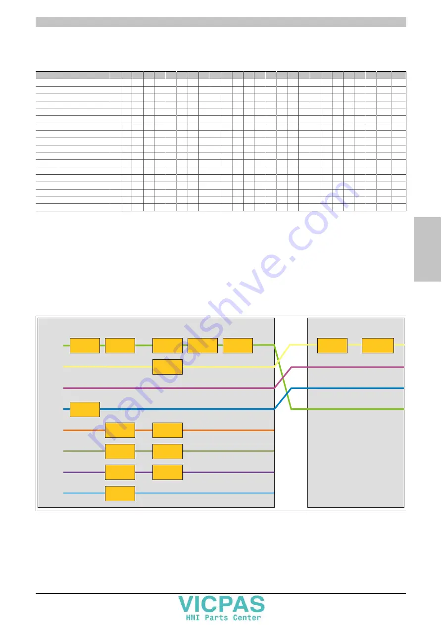
PIRQ A
IRQ 16
CPU board
UHCI 0
USB port 1&2
CPU board
GMA500
Graphics controller
Root 1
PCIe
Ethernet
PCIe 82574
USB client
SDIO 0
Not used
SDIO 1
SD port
SDIO 2
Not used
UHCI 1
USB port 3&4
IO board
UHCI 2
5&6 front / SDL
LPC
IF board
Bridge
PCIe to PCI
Fieldbus
POWERLINK,
X2X, CAN
PIRQ B
IRQ 17
PIRQ C
IRQ 18
PIRQ D
IRQ 19
PIRQ E
IRQ 20
HDA
Audio
Root 2
PCIe
EHCI
PIRQ F
IRQ 21
PIRQ G
IRQ 22
PIRQ H
IRQ 23
Figure 132: Interrupt routing with enabled APIC - Beginning with BIOS version N0.15


