Technical data • Complete system
24
Power Panel 500 user's manual V1.40
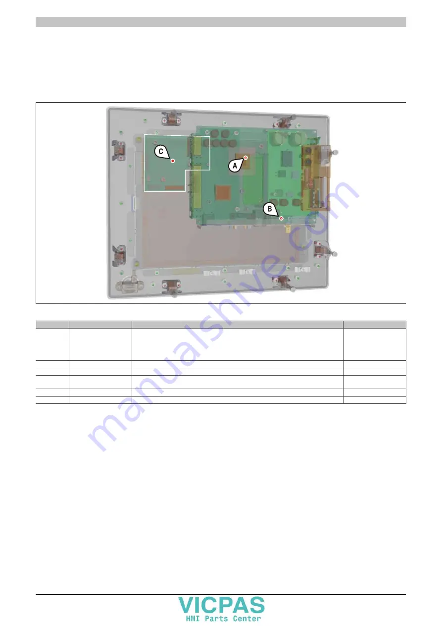
2.1.2 Temperature sensor locations
Sensors monitor temperature values at various locations (USB ports, main memory) inside the PP500. These tem-
peratures
2)
can be read in Microsoft Windows operating systems using the B&R Control Center
3)
or in Automation
Runtime using data points in Automation Studio.
For applications that don't use Windows, temperatures can be evaluated using the B&R implementation guide. In
addition to the implementation guide, there are also programs available in MS-DOS.
Figure 3: Temperature sensor locations
Position
Measurement point for Measurement
Max. specified
A
CPU
Ambient temperature of the processor (sensor integrated in the processor)
100°C:
5PP5CP.US15-00,
5PP5CP.US15-01
90°C: 5PP5CP.US15-02
A
Main memory
Ambient temperature of the main memory (sensor integrated in the processor)
80°C
B
Interfaces
Temperature of the interfaces (sensor integrated next to the USB ports)
80°C
C
Display
Temperature of the display (sensor integrated on the display board - the exact position de-
pends on the display diagonal)
80°C: Diagonals
5.7", 7", 10.4", 15"
Interface board
Temperature of an interface board (sensor integrated on the interface board)
Board-dependent
I/O board
Temperature of an I/O board (sensor integrated on the I/O board)
Board-dependent
Table 5: Temperature sensor locations
2)
The temperature measured approximates the immediate ambient temperature but may also be influenced by neighboring components.
3)
The B&R Control Center is included in the ADI driver, which is available in the Downloads section of the B&R website (www.br-automation.com).


