Technical data • Complete system
34
Power Panel 500 user's manual V1.40
2.5.9 Power button
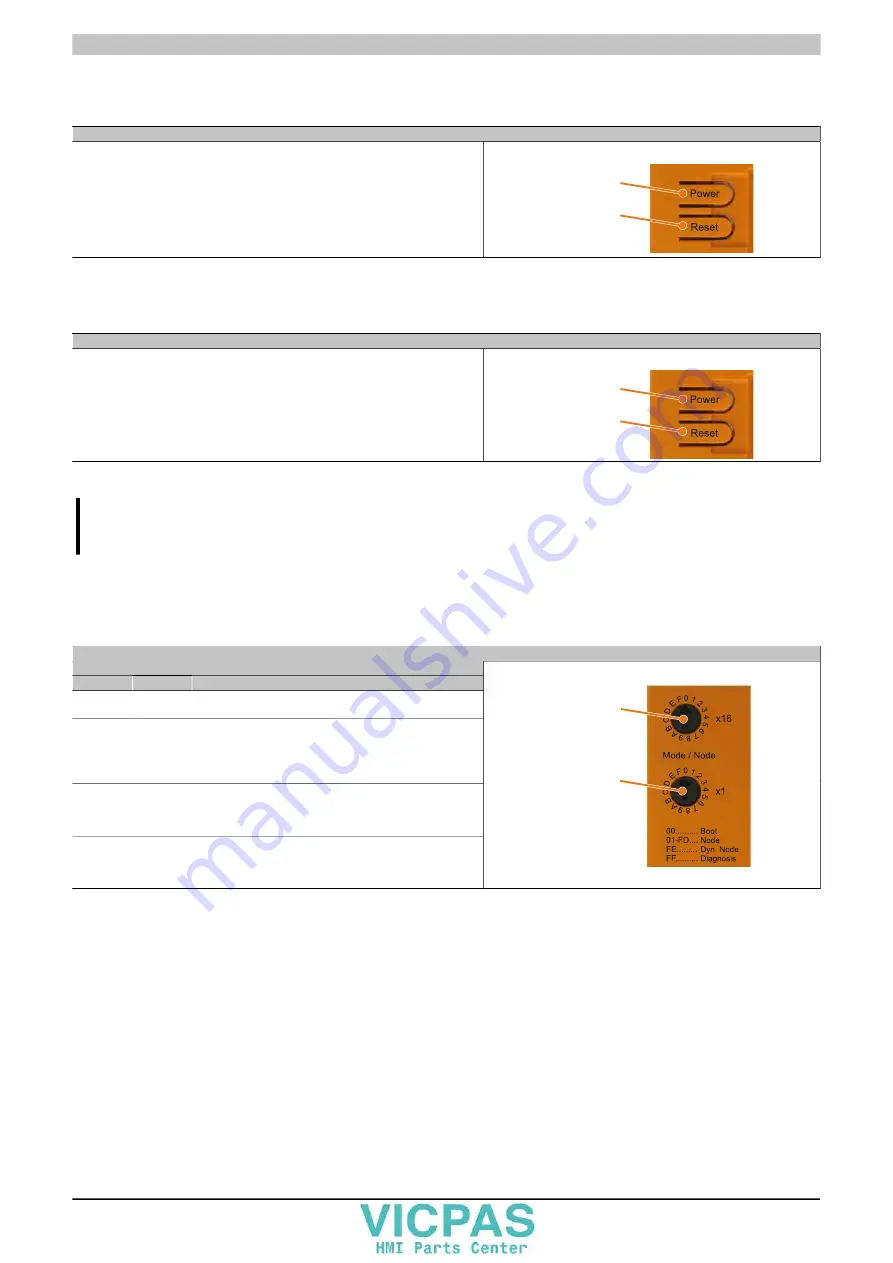
The power button provides a wide range of ATX power supply functions.
Power button
The power button acts like the on/off switch on a normal desktop PC with an ATX pow-
er supply:
Press and release
... Switches on the device or shuts down the operating system and
switches off the device
Press and hold
... Switches off the ATX power supply without shutting down the de-
vice (data could be lost!)
Pressing the power button does not reset the MTCX processor.
Power button
Reset button
Table 16: Power button
2.5.10 Reset button
Reset button
Pushing the reset button triggers a hardware and PCI reset.
The device is restarted (cold restart). Pressing the reset button does not reset the
MTCX processor.
Power button
Reset button
Table 17: Reset button
Warning!
A system reset can result in lost data!
2.5.11 Mode/Node switches
There are two 16-digit hex switches located on the back of the system unit that can be used as operating mode
switches. The user can use switch positions 01 to FD as needed and evaluate them in the application program.
Mode/Node switches
Switch position
x16
x1
Description
0
0
Boot
Default switch position. Not a terminal node switch position.
0...1
F...D
Node
Automation Runtime run mode with node 01-FD (Compact-
Flash Automation Runtime or terminal operation). Can be
used as needed, e.g. to set the INA2000 node number of the
Ethernet interface.
F
E
Dyn. node
Automation Runtime run mode with dynamic node assign-
ment (CompactFlash Automation Runtime or terminal opera-
tion). Device addresses can be assigned using software.
F
F
Diagnosis
Boots the device in diagnostic mode. Does not initialize pro-
gram sections in User RAM and User FlashPROM. After di-
agnostic mode, the CPU always boots with a cold restart.
Mode/Node
switch x16
Mode/Node
switch x1
Table 18: Mode/Node switches


