Technical data • Individual components
122
Power Panel 500 user's manual V1.40
Product ID
5PP5IO.GNAC-00
Environmental conditions
Temperature
Operation
0 to 50°C
Storage
-20 to 60°C
Transport
-20 to 60°C
Relative humidity
Operation
5 to 90%, non-condensing
Storage
5 to 95%, non-condensing
Transport
5 to 95%, non-condensing
Table 83: 5PP5IO.GNAC-00 - Technical data
1)
The COM2 interface is identified in BIOS as the COM D interface.
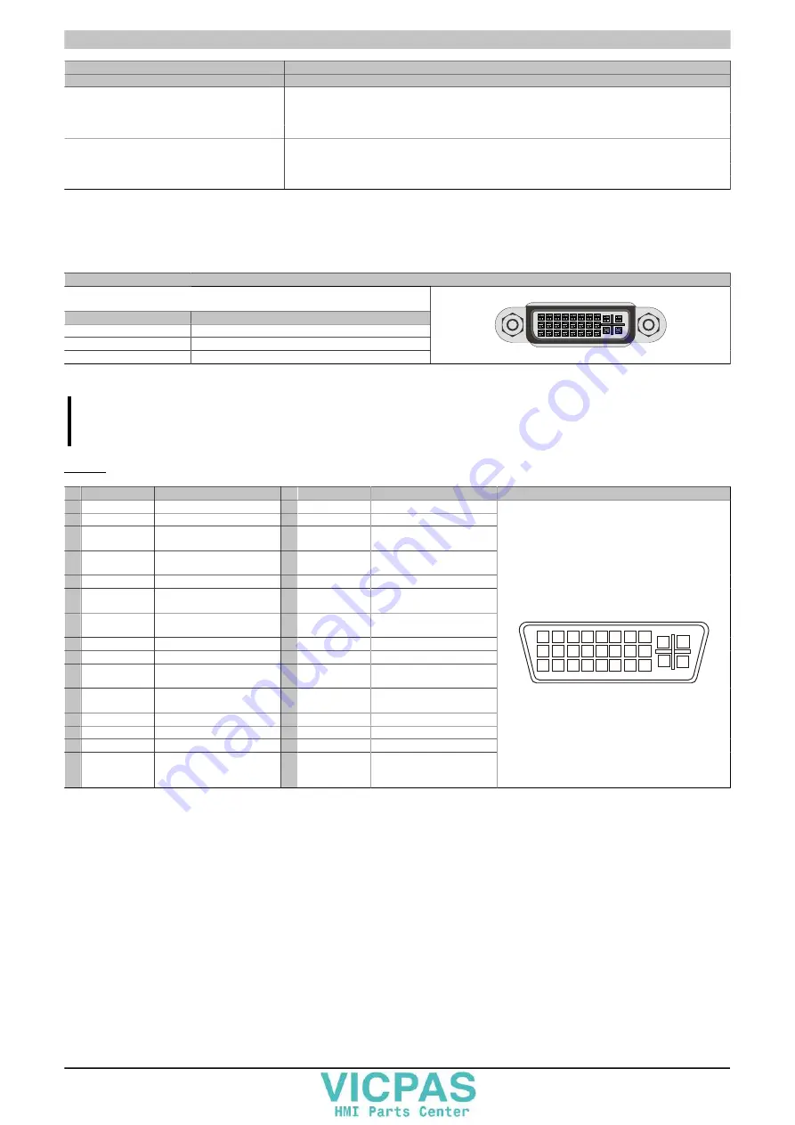
3.5.1.3.1 Panel interface - SDL (Smart Display Link) / DVI
Panel interface - SDL (Smart Display Link) / DVI
The following overview lists the video signals available on the panel output. For details,
see the technical data for the CPU board being used.
CPU board
Video signals with all system unit variants
5PP5CP.US15-00
DVI, SDL
5PP5CP.US15-01
DVI, SDL
5PP5CP.US15-02
DVI, SDL
Table 84: Panel interface - DVI, SDL
Information:
Only digital panels can be connected to the panel interface (analog monitors not permitted).
Pinout
Pin Assignment
Description
Pin Assignment
Description
1 TMDS data 2-
DVI lane 2 (negative)
16 HPD
Hot plug detect
2 TMDS data 2+
DVI lane 2 (positive)
17 TMDS data 0-
DVI lane 0 (negative)
3 TMDS data 2/4
SHIELD
Shield for data pair 2 and 4
18 TMDS data 0+
DVI lane 0 (positive)
4 SDL-
SDL lane (negative)
19 TMDS Data 0/
XUSB1 SHIELD
Shield for data pair 0 and
USB1
5 SDL+
SDL lane (positive)
20 XUSB1-
USB lane 1 (negative)
6 DDC clock
DDC-based control signal
(clock)
21 XUSB1+
USB lane 1 (positive)
7 DDC data
DDC-based control signal
(data)
22 TMDS clock
shield
Shield for clock pair
8 N/C
Not connected
23 TMDS clock+
DVI clock (positive)
9 TMDS data 1-
DVI lane 1 (negative)
24 TMDS clock -
DVI clock (negative)
10 TMDS DATA 1+ DVI lane 1 (negative) HDMI
clock (positive)
C1 N/C
Not connected
11 TMDS DATA 1/
XUSB0 SHIELD
Shield for data pair 1 and
USB0
C2 N/C
Not connected
12 XUSB0-
USB lane 0 (negative)
C3 N/C
Not connected
13 XUSB0+
USB lane 0 (positive)
C4 N/C
Not connected
14 +5 V power
1)
+5 V power supply
C5 N/C
Not connected
15
Ground (return
for +5 V, HSync
and VSync)
Ground
24-pin female DVI connector
6 7 8
5
1 2 3 4
14 15 16
13
9 10 11 12
22 23 24
21
17 18 19 20
c1
c4
c2
c3
c5
Table 85: DVI interface - Pinout
1)
Protected internally by a multifuse.


