Technical data • Complete system
28
Power Panel 500 user's manual V1.40
2.5 Device interfaces and slots
2.5.1 Overview of device interfaces
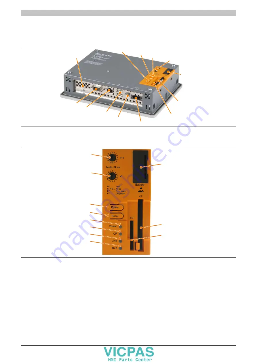
Interfaces for system units with an interface board
Ground connection
+24 VDC power supply
Ethernet 10/100/1000
COM RS232
Interface board
slot
SD memory card slot
CompactFlash slot
Battery
Mode/Node switches
Power button
Reset button
LED status indicators
USB1, USB2
Figure 7: Interfaces with an interface board
Back cover of the system unit
Mode/Node
switch x16
Mode/Node
switch x1
Power button
Reset button
Power LED
CF LED
Link LED
Run LED
Battery
CompactFlash
slot
SD memory card
slot
Figure 8: Back cover


