Device description
30
Power Panel C50 User's manual V1.10
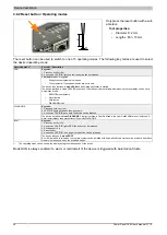
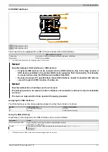
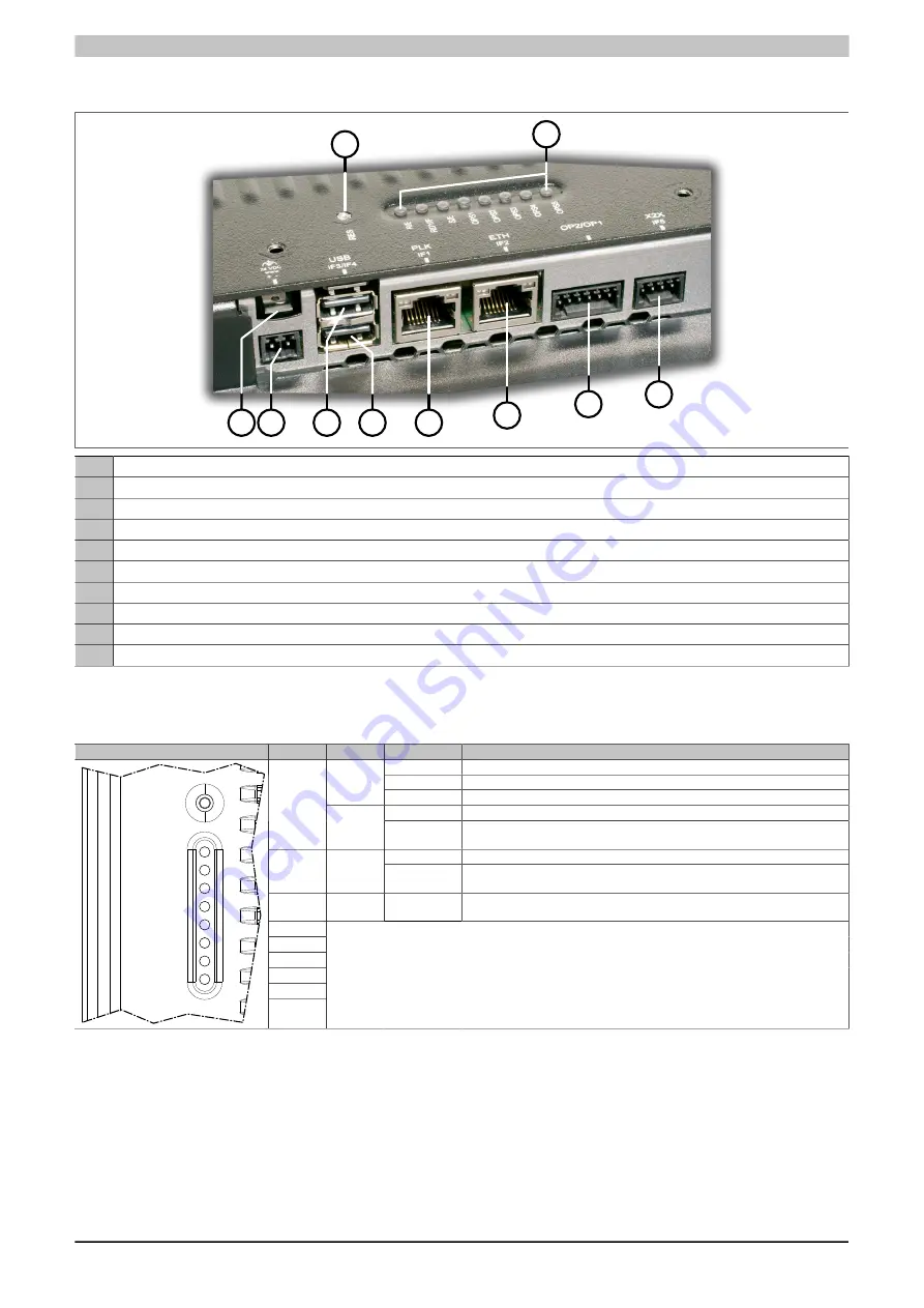
4.8 Operating and connection elements
1
2
3 4
5
6
7
8
9
10
1
Reset button
2
Diagnostic LED status indicators
3
Grounding clip
4
Power supply
5
IF3: USB interface
6
IF4: USB interface
7
IF1: POWERLINK interface
8
IF2: Ethernet interface
9
OP1/OP2: Fieldbus interfaces (depending on the Power Panel variant)
10
IF5: X2X Link interface
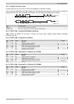
4.8.1 Diagnostic LED status indicators
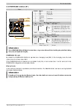
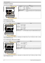
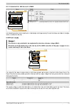
The following diagnostic LEDs are located on the back of the Power Panel C50:
Figure
LED
Color
Status
Description
On
Application running.
Double flash
Mode BOOT (during firmware update)
Green
Blinking
Mode BOOT (system startup)
On
Mode SERVICE or overtemperature shutdown
R/E
Red
Blinking
If LED "R/E" blinks red and LED "RDY/F" blinks yellow, a license violation has
occurred.
On
Mode SERVICE or BOOT.
RDY/F
Yellow
Blinking
If LED "R/E" blinks red and LED "RDY/F" blinks yellow, a license violation has
occurred.
S/E
Green/
Red
LED "Status/Error" for the POWERLINK interface.
For a description, see section
"LED "S/E" (LED "Status/Error")" on page 31
OPS1
OPS2
OPS3
OPS4
OPS5
RES
R/E
RDY/F
S/E
OPS1
OPS2
OPS3
OPS4
OPS5
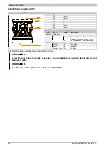
These LEDS have a different meaning depending on the Power Panel variant.
See the description in the following sections:
•
"OPS" LEDs - Variant without fieldbus interfaces
•
"OPS" LEDs - Variant with 2x CAN bus
•
"OPS" LEDs - Variant with 1x CAN bus and 1x RS232
•


