Device description
38
Power Panel C50 User's manual V1.10
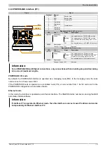
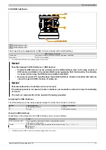
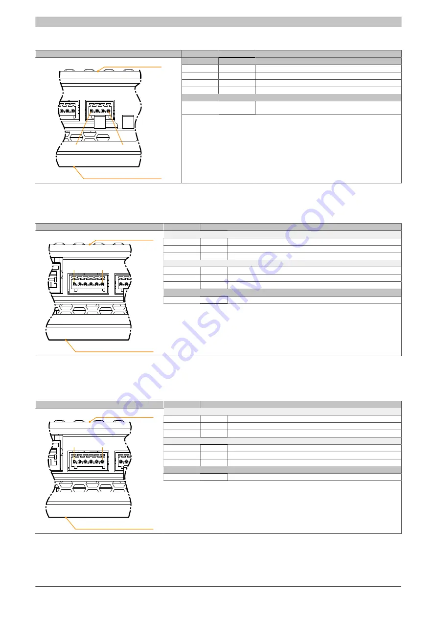
4.8.6 X2X Link interface
Figure
Pinout
Terminal
X2X Link
1
X2X
X2X data
2
X2X⊥
X2X ground
3
X2X\
X2X data inverted
4
SHLD
Shield
Required accessories
0TB5104.2110-01
Accessory terminal block, 4-pin (2.5), cage clamp terminal block
0.5 mm
2
1
4
Front (touch screen)
Back
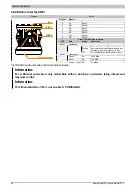
4.8.7 Fieldbus interfaces
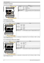
4.8.7.1 Variant with 2x CAN bus
Figure
Terminal
Pinout
IF7: CAN bus
1
CAN_H CAN high
2
GND
Ground
3
CAN_L
CAN low
IF6: CAN bus
4
CAN_H CAN high
5
GND
Ground
6
CAN_L
CAN low
Required accessories
0TB5106.2110-01
Accessory terminal block, 6-pin (2.5), cage clamp terminal block 0.5 mm
2
1
6
Front (touch screen)
Back
A terminating resistor can be switched on individually and independently for each interface via software (configu-
ration in Automation Studio).
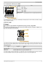
4.8.7.2 Variant with 1x CAN bus and 1x RS232
Figure
Terminal
Pinout
IF8: RS232
1
TxD
Transmit signal
2
GND
Ground
3
RxD
Receive signal
IF6: CAN bus
4
CAN_H CAN high
5
GND
Ground
6
CAN_L
CAN low
Required accessories
0TB5106.2110-01
Accessory terminal block, 6-pin (2.5), cage clamp terminal block 0.5 mm
2
1
6
Front (touch screen)
Back
A terminating resistor can be switched on individually and independently for each interface via software (configu-
ration in Automation Studio).


