


Device description
Power Panel C50 User's manual V1.10
39
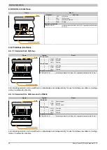
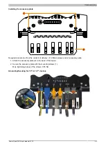
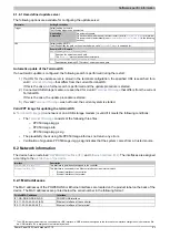
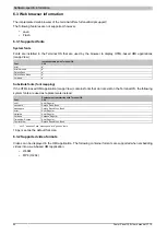
4.8.7.3 Variant with 1x CAN bus and 1x RS485
Figure
Terminal
Pinout
IF9: RS485
1
DATA
Data
2
GND
Ground
3
DATA\
Data inverted
IF6: CAN bus
4
CAN_H CAN high
5
GND
Ground
6
CAN_L
CAN low
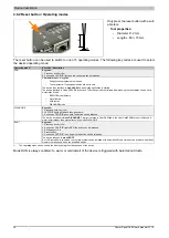
Required accessories
0TB5106.2110-01
Accessory terminal block, 6-pin (2.5), cage clamp terminal block 0.5 mm
2
1
6
Front (touch screen)
Back
A terminating resistor can be switched on individually and independently for each interface via software (configu-
ration in Automation Studio).
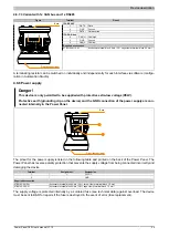
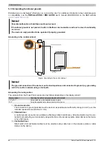
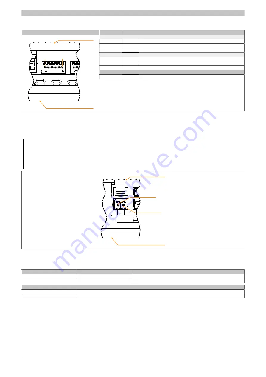
4.8.8 Power supply
Danger!
This device is only permitted to be supplied with protective extra-low voltage (PELV).
Protective earth (grounding clip on the device) and the GND connection of the power supply are con-
nected internally in the Power Panel.
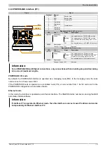
Front (touch screen)
Back
①
②
The pinout for the power supply is listed in the following table and printed on the back of the Power Panel. The
Power Panel has reverse polarity protection that prevents the supply voltage from being connected incorrectly and
damaging the device.
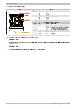
Terminal
Assignment
Explanation
1
+
24 VDC
2
−
GND
Required accessories
0TB6102.2010-01
Accessory terminal block, 2-pin (3.81), screw clamp terminal block 1.5 mm²
0TB6102.2110-01
Accessory terminal block, 2-pin (3.81), cage clamp terminal block 1.5 mm²
The supply voltage is protected internally by a soldered fuse (see technical data) against overload. The device
must be sent to B&R for repairs if the fuse is destroyed in the event of error (fuse replacement).


