


Commissioning
Power Panel C50 User's manual V1.10
41
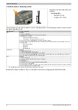
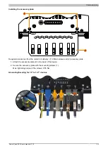
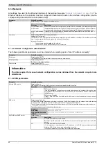
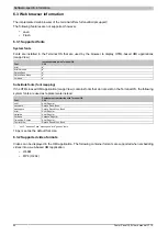
5.1.2 Mounting with retaining clips
Figure: Retaining clip
The retaining clips are designed for a certain thickness of the material
to be clamped (max. 6 mm, min. 2 mm).
A large flat-blade screwdriver is needed to tighten and remove the
screws.
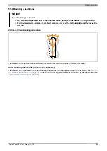
Devices must be installed on a flat, clean and burr-free surface; tight-
ening screws on an uneven area can result in damage to the display or
the ingress of dust and water.
See also
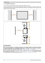
"Installation cutout requirements" on page 40
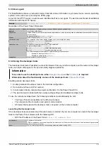
Procedure
1. Insert the device into the front of the prepared, burr-free and flat installation cutout. For the dimensions of the
installation cutout, see section "Dimensions" for the individual devices.
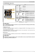
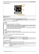
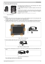
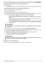
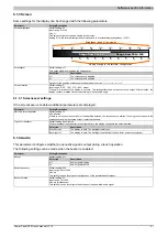
2. Install the retaining clips on the device. To do this, insert the clips into the openings on the sides of the device
(indicated by the orange circles). The number of openings may vary depending on the size of the device.
Figure: Using the retaining clips
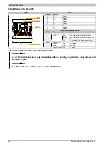
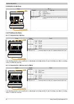
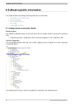
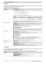
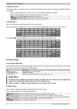
3. Slide the retaining clips all the way to the back of the openings.
Figure: Sliding the retaining clips back
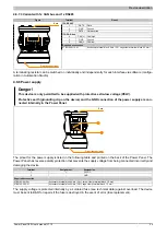
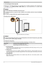
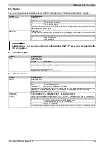
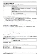
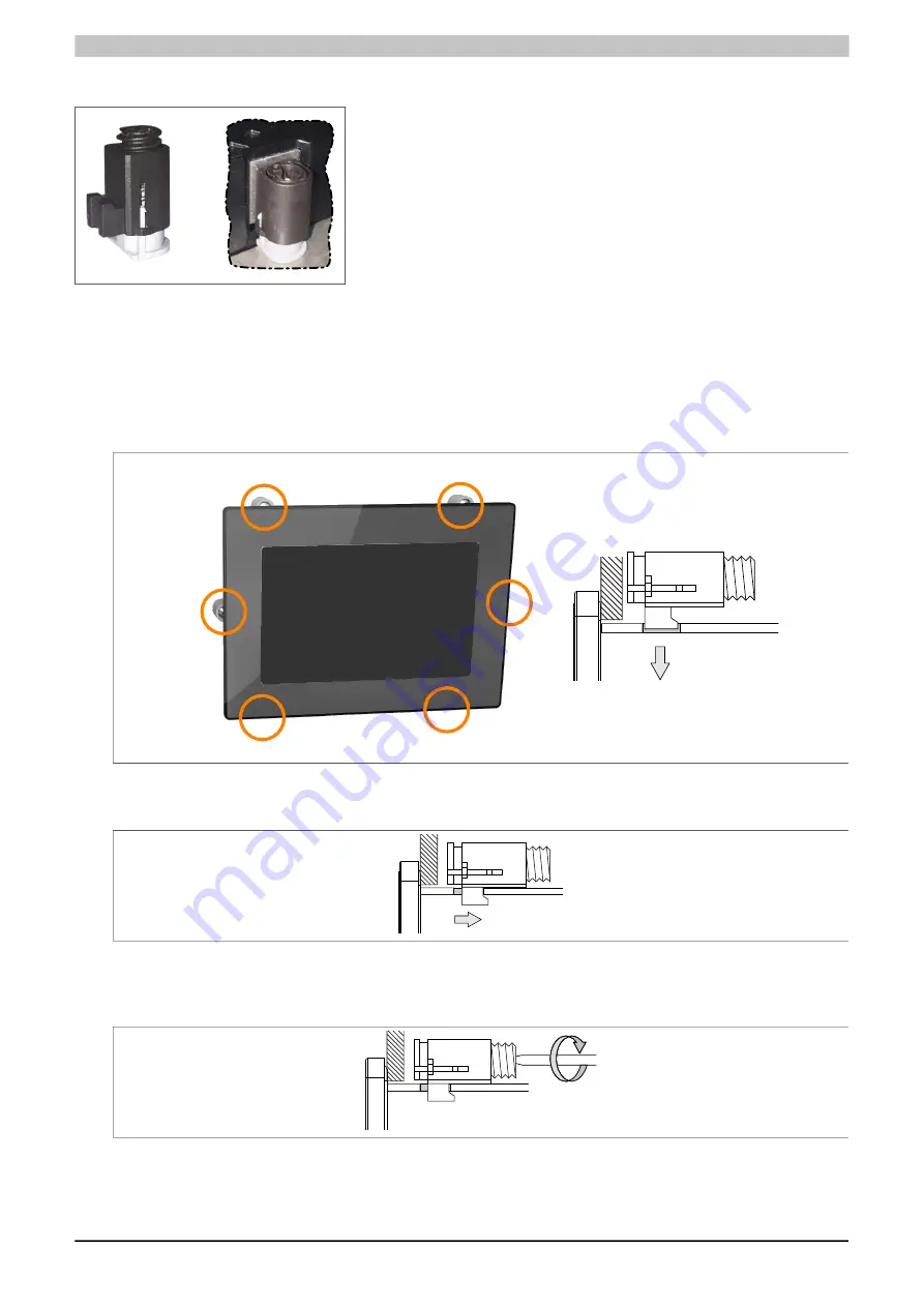
4. Now secure the retaining clips to the wall or control cabinet by tightening the screws with a flat-blade screw-
driver.
Figure: Securing the retaining clips
Torque limiting is built into the retaining clips.


