Commissioning
84
Power Panel C70 User's manual V1.30
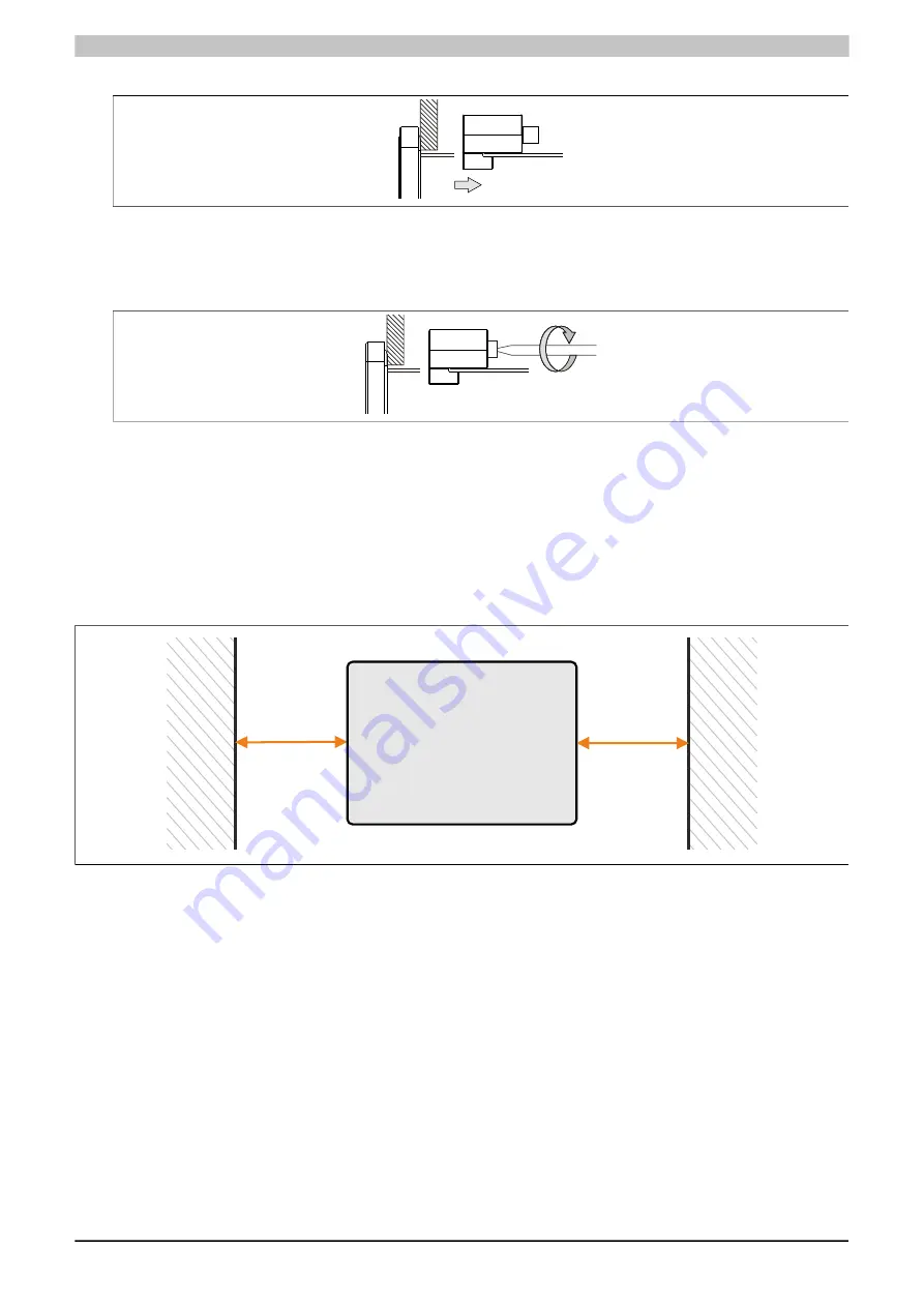
3. Slide the retaining clips all the way to the back of the openings.
Figure: Sliding the retaining clips back
4. Now secure the retaining clips to the wall or control cabinet by tightening the screws with a flat-blade screw-
driver.
Tightening torque: 0.4 Nm
Figure: Securing the retaining clips
4.1.3 Installation instructions
The Power Panel must be mounted using the retaining clips included in delivery (tightening torque: 0.4 Nm).
In order to ensure sufficient air circulation, the specified clearance values must be observed above, below, to the
side and behind the Power Panel. The minimum specified spacing is indicated in the following schematic diagrams.
This applies to all Power Panel variants.
Air circulation - Rear view
>40 mm
>40 mm


