X90 mobile modules
X90 mobile system User's manual V 1.20 - Translation of the original manual
117
5.2.2.12.4 Physical configuration of I/O channels
These registers define the function of the channels. Depending on the desired configuration, the following assign-
ments can be made with respect to the existing software and hardware:
•
One physical configuration as input or output
•
An explicit assignment as digital or analog input
•
An explicit assignment of input impedance (only for digital inputs)
•
An explicit assignment as PWM output
•
An explicit assignment as parallel output
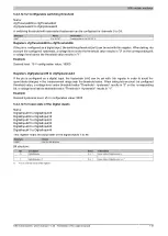
5.2.2.12.4.1 Physical configuration
Name:
cfgPinMode01 to cfgPinMode08
cfgPinMode09 to cfgPinMode24
cfgPinMode25 to cfgPinMode32
cfgPinMode33 to cfgPinMode48
These registers configure the function of the channels.
Channels 1 to 8 can only be used as digital inputs.
Data type
Values
Information
0
Off (default)
30
Digital input source 6.5 kΩ
31
Digital input source 9 kΩ
32
Digital input source 18 kΩ
40
Digital input sink 6.5 kΩ
41
Digital input sink 9 kΩ
USINT
42
Digital input sink 18 kΩ
Channels 9 to 24 can be configured as both digital inputs as well as analog inputs.
Data type
Values
Information
0
Off (default)
50
Digital input with voltage measurement diagnostics
51
Digital input with current measurement diagnostics
60
Digital input, source / 6.5 kΩ, pull-up with adjustable switching threshold
61
Digital input, source / 9 kΩ, pull-up with adjustable switching threshold
62
Digital input, source / 18 kΩ, pull-up with adjustable switching threshold
70
Digital input, sink / 6.5 kΩ, pull-down with adjustable switching threshold
71
Digital input, sink / 9 kΩ, pull-down with adjustable switching threshold
72
Digital input, sink / 18 kΩ, pull-down with adjustable switching threshold
80
Analog input 0 to 10 V
81
Analog input 0 to 32 V
USINT
82
Analog input 0 to 20 mA
Channels 25 to 32 can be configured as both digital inputs as well as digital outputs. Parallel connection is possible
when configured as a digital output.
A maximum of 2 adjacent outputs are permitted to be connected in parallel on the outputs (1 main output, 1 parallel
output). In addition, only uneven channel numbers can be main outputs. Parallel connections are not possible via
inputs.
Data type
Values
Information
0
Off (default)
1
Digital main output
20
Digital parallel output
31
Digital input in source configuration with 9 kΩ input resistance
USINT
41
Digital input in sink configuration with 9 kΩ input resistance
Channels 33 to 48 can be configured as both digital inputs as well as digital outputs. The outputs support PWM.
Parallel connection is possible when configured as a digital output. A parallel connection is only possible with
adjacent outputs. This approach begins with the pin with the smallest number.


