X90 mobile modules
40
X90 mobile system User's manual V 1.20 - Translation of the original manual
Model number
X90CP172.24-00
X90CP172.48-00
Mechanical properties
Dimensions
Width
250 mm
Length
231 mm
Height
44 mm
Brief overview
Content of delivery
2x threaded caps for unused M12 female connectors
Table 10: X90CP172.24-00, X90CP172.48-00 - Technical data
1)
Connected to the capacitor and 60 V VDR protective element.
2)
CPU and I/O power supply connected externally.
3)
Can be set in Automation Studio.
4)
Based on the current measured value.
5)
Based on the 10 V or 32 V measurement range.
6)
Based on the 20 mA measurement range.
7)
At 10 V sensor power supply, the CPU power supply must be ≥12 VDC.
8)
The current can be reduced to 200 mA depending on the option board being used.
9)
For additional information about parallel connections, see chapter "Derating".
10)
Sum of MF-DO + MF-PWM
11)
Applied only if mating connector (M12/CPC) connected or with M12 protective covers (0.6 Nm torque).
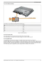
5.2.1.4 LED status indicators
Figure
LED
Color
Status
Description
On
Application running
Green
Blinking
System startup boot mode:
CPU initializing the application, all bus systems and I/O modules
1)
On
Mode SERVICE
Blinking
LED "R/E" blinks red and LED "RDY/F" blinks yellow when there is a license
violation.
R/E
Red
Double flash
Mode BOOT (during firmware update)
1)
On
Mode SERVICE or BOOT
RDY/F
Yellow
Blinking
LED "RDY/F" blinks yellow and LED "R/E" blinks red when there is a license
violation.
On
A link to the Ethernet remote station has been established.
ETH
Green
Blinking
A link to the Ethernet remote station has been established. The LED blinks if
Ethernet activity is taking place on the bus.
1)
This process can take several minutes depending on the configuration.


