background image

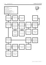
Adjustments     3.3

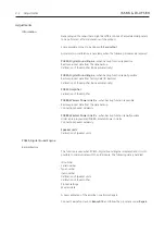
ID Restore

The ID Restore function is used when PCB30, Digital Sound Engine is replaced and 
it is 

not

 possible to communicate with the old module. In this case it is necessary 

to get product data from the ServiceTool (factory data from a database). The 

following is automatically transferred:

-  ID number
-  Serial number
-  Type number
-  Item number
-  Calibration of speaker units
-  Product settings

-  A new calibration of the amplifier is performed again.

Connect ServiceTool, launch 

BeoLab 19

 and follow the procedure under 

Repair.

PCB35, Amplifier

Calibration of the amplifier

Calibration of the amplifier is necessary when PCB35, Amplifier is replaced. The 

aim is to ensure optimal sound. 

Connect ServiceTool, launch 

BeoLab 19

 and follow the procedure under 

Adjustments.

PCB89, Wireless Power Link Rx

Backup/Restore

This function is used when PCB89, Wireless Power Link Rx is replaced and it is still 
possible to communicate with the old module. The following data is handled:

-  ID number
-  Serial number
-  Type number
-  Item number
-  Calibration of speaker units

-  Calibration of the amplifier

-  Product settings
-  Wireless data

-  A new calibration of the amplifier is performed again.

Connect ServiceTool, launch 

BeoLab 19

 and follow the procedure under 

Repair.

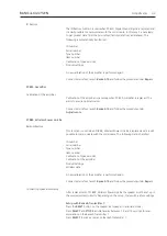
Connecting speaker wirelessly

After replacement of PCB89, Wireless Power Link Rx the speaker must be set up in 
the wireless system correctly. Depending on the setup, there will be a few settings.

Setup with BeoLab Transmitter 1:

-  Press the 

RESET

 button on the speaker (set speaker in associate mode)

- Press 

SELECT

 and 

STORE

 simultaneously between 1.5 and 10 seconds to reset 

association on the BeoLab Transmitter 1

- Press 

SELECT

 to make a rescan on BeoLab Transmitter 1.

Summary of Contents for BeoLab 19

Page 1: ...ice Manual version 1 0 English German French Italian Spanish Dutch Japanese Korean and Simplified Chinese versions are available in the Retail System This Service Manual must be returned with the defe...

Page 2: ...to service 1 2 Troubleshooting Fault flow chart 2 1 Adjustments 3 1 Replacement of modules 4 1 Specification guidelines for service use 5 1 Block diagram 6 1 Wiring diagram 6 3 Available parts 7 1 Ch...

Page 3: ...s PCB02 Connector PCB04 Power Supply PCB05 Energy Buffer PCB30 Digital Sound Engine PCB35 Amplifier PCB47 LED Indicator PCB48 NTC PCB89 Wireless Power Link Rx Speaker units Front woofer Back woofer 05...

Page 4: ...iring the module s and must be returned with the defective module s Handling the error code error log a Make a note of the error code codes on the Exchange Module section and print it b Use the error...

Page 5: ...void getting injured by mains voltage ESD ESD Mat STATIC ELECTRICITY MAY DESTROY THE PRODUCT Waste of Electrical and Electronic Equipment WEEE Electrical and electronic equipment parts and batteries m...

Page 6: ...1 4...

Page 7: ...4 NTC module test 2 4 Sound test 2 5 Fault flow chart No function and no LED indication 2 6 LED indicator is constant orange 2 7 LED indicator is flashing slowly orange 2 8 LED indicator is flashing...

Page 8: ...dy for pairing Orange Solid The signal strenght for wireless connection is low Flashing slowly The product is close to overheating and will shut down temporarily The product will eventually revert to...

Page 9: ...t a service PC with ServiceTool Follow the procedure below Connect the ServiceTool to the SERVICE connector on the product as shown Run ServiceTool Be sure that ServiceTool is updated to the latest ve...

Page 10: ...ive and must be replaced Under normal conditions it is not necessary to replace the gaskets on the speaker unit unless they have been damaged by accident NTC module test Measure the resistance of the...

Page 11: ...s the user to send a pure sound directly to the speaker unit This feature makes troubleshooting or testing more easy and targeted Run ServiceTool Be sure that ServiceTool is updated to the latest vers...

Page 12: ...he wireless connection between the speaker and the transmitter is OK OK Repair set up the wireless connection Repair replace connection Confirm mains voltages at PCB04 P1 pin 1 2 OK Replace PCB04 Powe...

Page 13: ...12 m Reposition either transmitter or speaker Yes Confirm that the distance between the transmitter and the speaker is less than the recommended 12 meters OK Tip Use Wi Spy Wi Spy DBx Chanalyzer Pro t...

Page 14: ...K Read out the temperature of the woofer Seems normal Replace PCB48 NTC Measure the DC resistance of the woofer wires disconnected Woofer 5 3 1 OK Read out the temperature Seems normal Replace PCB35 A...

Page 15: ...temperature PCB35 Amplifier Tip Use ServiceTool to read out Error Log Replace the suspected module related to the Error Log Connect ServiceTool and read out product ID Confirm all product ID data is c...

Page 16: ...t PCB05 P1 pin 7 8 OK Replace PCB04 Power Supply Replace PCB05 Energy Buffer Repair replace connection W3 between PCB04 Power Supply and PCB05 Energy Buffer Replace PCB30 Digital Sound Engine Confirm...

Page 17: ...PCB30 Digital Sound Engine OK Repair replace connection W2 Confirm 1 6V at PCB89 P7 pin 22 and 3 3V at PCB89 P7 pin 24 OK Connect ServiceTool and read out Error Log Any suggestions Replace PCB89 Wire...

Page 18: ...ce PCB04 Power Supply Replace PCB05 Energy Buffer Repair replace connection W3 between PCB04 Power Supply and PCB05 Energy Buffer Replace PCB30 Digital Sound Engine Confirm 3V at PCB04 P3 pin 3 OK Che...

Page 19: ...9 Wireless Power Link Rx 1 8 3 1 1 11 P4 P3 P5 P1 1 8 3 1 1 11 P4 P3 P5 P1 P1 P1 P2 8 1 9 1 P1 P2 8 1 9 1 P1 P2 8 1 9 1 04 28V 28V NC GNDA GNDA NC 28V 28V 8 7 6 5 4 3 2 1 28V 28V NC GNDA GNDA NC 28V 2...

Page 20: ...2 14 2 14 2 14...

Page 21: ...Adjustments 3 1 Adjustments Information 3 2 PCB30 Digital Sound Engine 3 2 PCB35 Amplifier 3 3 PCB89 Wireless Power Link Rx 3 3 Speaker units 3 4 Software update 3 4 Final check after repair 3 5...

Page 22: ...ier Calibration of the amplifier PCB89 Wireless Power Link Rx when backup function is possible Restore product data from the data backup Connecting speaker wirelessly PCB89 Wireless Power Link Rx when...

Page 23: ...nder Adjustments PCB89 Wireless Power Link Rx Backup Restore This function is used when PCB89 Wireless Power Link Rx is replaced and it is still possible to communicate with the old module The followi...

Page 24: ...ick on the PRODUCT tab if not already shown Click next to each item to expand the menus Click Software Automatic Software Update Follow the procedure in ServiceTool I O Setup with product equipped wit...

Page 25: ...voltage level for one second then slowly decrease the voltage to 0 V ac Restore setup Before the product is handed over to the customer ensure that The position switch FREE WALL CORNER is in correct p...

Page 26: ...3 6...

Page 27: ...o the new module after replacement Refer to adjustment page 3 2 After replacement of PCB30 Digital Sound Engine the new module must be updated to the latest software version Refer to page 3 4 After re...

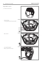
Page 28: ...es Turn around the speaker Remove rubber feets and screws Disconnect cables Unlock plugs before disconnecting cables Remove screws 02P103 02P101 02P102 Replace PCB02 Connector 4 15 Remove back woofer...

Page 29: ...et all switches in down position When reassembling all switches must be in down position Gently pull off connector well Remove screws and replace PCB02 Connector Move EMC gaskets to the new PCB or mou...

Page 30: ...include washers Remove screws and wireclips 2x TX20 8mm 2x TX20 8mm Disconnect cable Use peeler tool to unlock and disconnect cable Use peeler tool to unlock 04P1 Replace PCB04 Power Supply 4 14 Remo...

Page 31: ...ntly move out and turn up the socket side of PCB04 Power Supply Disconnect cables and pull out module 04P5 04P4 04P3 Remove screws and replace PCB04 Power Supply Gently move gap pads to new PCB or mou...

Page 32: ...4 6 Replacement of modules Remove screws and replace PCB05 Energy Buffer Disconnect cables 4x TX10 5mm 05P2 05P1 Replace PCB05 Energy Buffer 4 14 Remove front woofer...

Page 33: ...cables Remove tape and flat cables from aluminium plate and wall 2x TX20 8mm Remove nut and gently turn out module Attention cables Remove 3 washers underneath metal plate When reassembling remember...

Page 34: ...8mm Remove screws and pull off metal plate Note placement of wireclips Remove screws Disconnect cables Unlock plugs before disconnecting cables Disconnect cables and gently pull out modules and flat c...

Page 35: ...Replacement of modules 4 9 2x TX10 8mm 2x 5 5mm 12mm 2x 5 5mm 18mm Remove screws and standoffs Remove standoffs Gently disconnect pull off and replace PCB30 Digital Sound Engine 30P7...

Page 36: ...odules Remove screws and replace PCB35 Amplifier Screws include washers Gently move gap pads to new PCB or mount new if damaged Disconnect cables 6x TX10 5mm 35P3 35P2 35P1 Replace PCB35 Amplifier 4 1...

Page 37: ...es 4 11 Remove screws 2x TX10 8mm Gently pull off module Disconnect cable and replace PCB47 LED Indicator Gently move gasket to new PCB or mount new if damaged Gasket 47P41 Replace PCB47 LED Indicator...

Page 38: ...4 12 Replacement of modules 1x TX10 6mm Replace PCB48 NTC 4 14 Remove front woofer Remove screw and replace PCB48 NTC...

Page 39: ...nt of modules 4 13 Remove screws and replace PCB89 Wireless Power Link Rx Replace PCB89 Wireless Power Link Rx 4 14 Remove front woofer 4 15 Remove back woofer 4 7 Remove PCB30 Digital Sound Engine 2x...

Page 40: ...oofer and disconnect wires Remove screw and NTC module and replace woofer When reassembling remember to mount woofer with terminals in correct position Terminals on woofer must be alligned to marks on...

Page 41: ...woofer with terminals in correct position Terminals on woofer must be alligned to marks on shell Gently pull out woofer Disconnect wires and replace back woofer Remove screws Screws include washers S...

Page 42: ...4 16...

Page 43: ...e 0 180 setting Wireless Power Link Wireless Technology WiSATM 5 GHz EFFECTIVE FREQUENCY RANGE is measured at 10 dB re Ref level 200 2000 Hz SENSITIVITY is measured at dB SPL 1 m re 125 mV Market Vari...

Page 44: ...al GND Pin 4 Speaker ON on 2 5V off 0 5V via source Pin 5 Not used PL power up Pin 6 Audio Right in Pin 7 Signal GND Pin 8 Audio Left in SERVICE RJ45 socket Pin 1 Not used Pin 2 ATI_TX Pin 3 ATI_RX Pi...

Page 45: ...G0 nDET1 3V3 P7 Wireless Power Link Rx P7 Tweeter Woofer PCB30 Digital Sound Engine PCB04 Power Supply PCB48 NTC PCB47 LED Indicator PCB02 Connector PCB35 Amplifier PCB89 Wireless Power Link Rx A MUX...

Page 46: ...6 2 6 2 6 2...

Page 47: ..._AMP 1_G ND_SEN SE CO N_AMP1_CH 2_P CO N_AMP 1_CH 2_N GND CO N_AMP 1_E N_N CO N_AMP1_DC_ N CO N_MONITO R1 CO N_MONITO R2 CO N_AMP1_NTC 1 CO N_AMP1_NTC 2 CO N_AMP 2_G ND_SEN SE CO N_AMP2_CH 1_P CO N_AM...

Page 48: ...al Sound Engine See Connector well Incl pos no 9004 9005 1 1 1 1 1 1 1 1 2 2 2 2 2 2 2 2 3 4 3 4 3 4 3 4 3 4 3 4 13 13 2 2 2 2 2 7 7 11 9 1 2 1 2 1 2 1 2 1 2 1 2 1 2 1 2 3 3 3 3 5 5 5 5 5 6 6 6 6 6 6...

Page 49: ...3M 3376477 Mains cable Korea 2 5A 3M 3375119 Mains cable China 6A 3M 3376113 Mains cable TWN 2 5A 125V 3M 3376103 Mains cable TH 2 5A 3M 05Module 8007773 PCB05 Energy Buffer 35Module 8007783 PCB35 Am...

Page 50: ...y 04 Not for sale 15 15 15 15 15 15 16 16 16 16 16 16 17 17 18 18 18 18 15 15 15 15 15 15 04Module 8007784 PCB04 Power Supply Survey of screws etc 15 2042061 Screw 3 x 8mm 16 2934130 Standoff 17 26220...

Page 51: ...ne 89Module 8007804 PCB89 Wireless Power Link Rx 8345390 Pre prog PCB89 Wireless Power Link Rx Survey of screws etc 10 2013144 Screw 3 x 8mm 15 2042061 Screw 3 x 8mm 18 7530119 Cable tie 3 1mm 20 2934...

Page 52: ...7 5 Available parts Connector well 9015 02 Not for sale 10 9016 W1 9018 9018 9019 9017 9017 10 10 10 10 10 10 10 10 10 10 10 25 25 25...

Page 53: ...skets 9016 3459649 Connector well 9017 3160825 Knob 9018 3153048 Wire bracket 9019 3340377 Gasket 02Module 8007810 PCB02 Connector W1 6278891 Wire Mains inlet Survey of screws etc 10 2013144 Screw 3 x...

Page 54: ...ber to order new tape W6 6278894 Wire DSE AMP W7 6278892 Wire EB AMP W8 6278895 Wire AMP SPK Parts not shown 3376530 Product cover 3948048 Tape 6M Packing 3393999 Packing complete Back up suitcase 339...

Page 55: ......

Page 56: ...Bang Olufsen DK 7600 Struer Denmark 3538208 13 11 353820813110000...

Reviews: