background image

BANLAW PRODUCT DATA SHEET  


 DRY-BREAK DIESEL REFUELLING NOZZLES


Doc ID: PRH-REF-70      Version: 7.0 


Page 

22

 of 

32


Please ensure you have the latest version of this document.


5


PRINCIPLES OF OPERATION 


A  Banlaw  Nozzle  shall  only  be  used  by  trained  personnel,  deemed 
competent in its proper operation. 

The operation of a Nozzle by untrained 

persons introduces potentially serious health and safety risks. 


A  Banlaw  Nozzle  must  only  be  operated  in  accordance  with  Banlaw 
procedures.


Any incidents or problems involving the operation of the Nozzle 

 and the dry-

break refuelling system 

 should be promptly reported and investigated. 


Equipment that is damaged, leaking or otherwise unfit for operation must not 
be  used,  but  must  instead  be  replaced  or  repaired  prior  to  use  of  a  diesel 
refuelling system. 


It  is  recommended  the  refuelling  event  is  monitored  (supervised).

  In  the 

event of a system malfunction or other incident, this will allow personnel to 
react promptly to avoid further escalation of the hazards. 


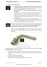
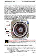
The  use  of  a  splash-fill  adaptor  (refer  Figure  22)  with  a  dry-break  refuelling  nozzle 
introduces additional hazards and risk. 

Persons must not use such an adaptor without 

being trained on the additional safe operating requirements for this task.  


Banlaw Recommends


“Designing 

Out


the requirement to refuel with such Splash-fill 

adaptors  wherever  possible.  Please  refer  to  Banlaw  document  BPA-27  for  further 
information. 


Figure 22 - Example of a Splash-Fill Adaptor


Refuelling couplings, e.g. nozzle and receiver, that are contaminated with dust and other build-up 

must 

be cleaned prior to use

. This will help prevent; 


Contamination entering the system, subsequently increasing the probability of system failure.  


Contamination from entering the fuel stream, increasing the probability of engine fuel system 
problems. 


Accelerated wear & tear of mating parts. 


Damage to fluid seals, creating fuel leakage. 


Difficulty in properly engaging/connecting the nozzle and receiver. 


Summary of Contents for 800 Series

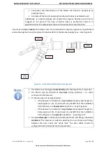
Page 1: ...refers to the maximum rated diesel flowrate of 1000LPM 264GPM of the 1000 series Banlaw Nozzles are available in a variety of models variants within each series including the Banlaw FuelTrack Nozzles...

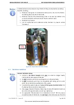
Page 2: ...lity nor liability for the consequences and damages that may occur in the execution of works within this document Persons conducting or otherwise involved with the execution of the works within this d...

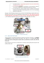
Page 3: ...supplement complement a Quick Fill System but where the OFP system acts as the primary first means of terminating the inflow of liquid into the tank without the need for pressurisation of the tank s...

Page 4: ...the Nozzle will automatically shut off and decreasing the spring setting will decrease the pressure required for shut off 1 2 System Overview Banlaw Dry Break Diesel Refuelling Nozzles are a key comp...

Page 5: ...pplications Banlaw 800 model Mining series Nozzles e g BNM800M suit all industry standard Receivers e g Wiggins ZN2 JNX series Caterpillar FloMAX FR series etc Industry proven ball lock latching mecha...

Page 6: ...re 5 illustrates the key external features of a Banlaw refuelling nozzle Figure 5 Key External Features of Banlaw Nozzle 1 4 Part Numbering Figure 6 and Figure 7 denotes the part numbering system used...

Page 7: ...5 Available Nozzle Models The 800 Nozzle series currently consists of 12 different models whilst the 1000 Nozzle series consists of 4 models as per Table 1 Please refer to Banlaw Sales Marketing mater...

Page 8: ...cifically the setting specification of the piston spring Banlaw document EBL 33 provides further important information on spring settings Selection of the required Spring Setting should be performed p...

Page 9: ...e and Receiver spring settings Figure 10 Relationship Between Nozzle and Receiver Spring Settings Figure 11 illustrates the location on a Nozzle where the Spring Setting is marked Figure 11 Example of...

Page 10: ...5 kPa Please refer to the Product Data Sheet PRH REF 72 for information on Receiver spring settings 1 7 FuelTrack Nozzle Variants Figure 12 illustrates the basic architecture of the Banlaw FuelTrack...

Page 11: ...COMPATIBILITY Nozzles Series Receivers Series Banlaw 800 Mining Banlaw 23 Mining Wiggins ZN2 JNC2 JNX etc Caterpillar FloMAX International FR FRA FRS etc Fast Fill Systems R150 R150CV etc See also No...

Page 12: ...through the cooperation of the supplier OEM Banlaw and the customer or end user Once such an assessment deems the Banlaw product s to be suitable the customer or end user shall ensure effective change...

Page 13: ...nally acceptable after consultation with Banlaw b Banlaw Hydraulic Nozzles i e BNH800 series have traditionally been used with solcenic oils without incident 4 Banlaw Nozzles are not recommended for u...

Page 14: ...Steel Viton Nitrile NBR Acetal Fluorosilicone Nylon Process Connection Inlet 2 NPT F Mass of Nozzle approx 4 2kg 9 3lb Legend SWP Maximum recommended Safe Working Pressure LPM Litres per minute volum...

Page 15: ...ure Drop Through 1000 Nozzle and 43 Receiver Notes 1 All pressure drop data refers to the dynamic head loss through the Banlaw Nozzle and Banlaw Receiver combination This data will vary when a Banlaw...

Page 16: ...is being installed Failure to select the proper nozzle setting will increase the risk of hazards such as o Overfilling and the likely internal over pressurisation of the tank s o Spillage of fuel envi...

Page 17: ...igure 15 Basic Nozzle and Receiver Arrangement The Nozzle must be aligned concentrically with the Receiver for connection The Nozzle may be oriented at any angle during operation i e when connected to...

Page 18: ...ng a Banlaw Nozzle Holster or Nozzle Anchor or by fabricating a custom bracket to safely store the Nozzle The location of the holster etc shall allow safe convenient and ergonomic access by personnel...

Page 19: ...e interlocked with additional safety features to prevent vehicle driveaway General Installation Notes 1 Conduct a Job Hazard Analysis JHA prior to install to mitigate health environmental and equipmen...

Page 20: ...k series Nozzles e g BNMF800 and BNF1000 series During connection of the Swivel refer section 4 2 it is imperative the spring loaded male probe extending from the Swivel outlet is inserted into the fe...

Page 21: ...it 4 3 Commissioning Guidelines There are no specific commissioning requirements for a Banlaw Nozzle Banlaw do however recommend witnessing tank pressures and system performance during the initial ref...

Page 22: ...m malfunction or other incident this will allow personnel to react promptly to avoid further escalation of the hazards The use of a splash fill adaptor refer Figure 22 with a dry break refuelling nozz...

Page 23: ...erfill or other causes IF A TANK LEVEL GAUGE EXISTS FIRST DETERMINE WHETHER THE TANK S REQUIRES REFILLING I E FUEL LEVEL IS BELOW THE SAFE FILL LEVEL ENSURE NOZZLE OPERATING HANDLE IS SECURELY LATCHED...

Page 24: ...3SECS IF NOZZLE WILL STILL NOT REMAIN OPEN CONFIRM TANK IS NOT ALREADY FILLED TO CAPACITY IF NOT REFER SECTION 7 DO NOT MANUALLY OR OTHERWISE FORCIBLY HOLD THE OPERATING HANDLE IN THE ON OR PARTIALLY...

Page 25: ...or information contact Banlaw or refer to Banlaw document EBL 33 Refuelling operators who manually override the automatic tank pressure shut off function of Banlaw Nozzles by holding or using some dev...

Page 26: ...off A drive away i e movement of the plant equipment whilst the Nozzle remains connected 6 MAINTENANCE SPARE PARTS Spare parts including service kits for Banlaw Nozzles are only sold to accredited Ba...

Page 27: ...end of the Nozzle is more exposed to contamination ingress and general wear tear particularly if a Nozzle Anchor Holster or Dust Plug is not used to store the Nozzle Figure 24 illustrates the front e...

Page 28: ...all inline bulk filtration on all diesel dispensing lines contact Banlaw for advice 4 Maintain the use of the Receiver Dust Cap and Nozzle Anchors Holsters or Dust Plugs 5 Remove any contamination fro...

Page 29: ...safely store a Nozzle off the ground when not in use Please contact Banlaw or your nearest Banlaw agent for more detailed preventative maintenance information 6 2 Banlaw Onsite Maintenance Clients ca...

Page 30: ...ow recommended minimum Increase delivery flow rate Excessive free play mechanical wear in the Nozzles operating mechanism replace Nozzle and have faulty Nozzle serviced A component in the system has b...

Page 31: ...rly contaminated investigate and rectify Fluid Leakage between Nozzle and Receiver during Refuelling Faulty fluid seal s within Nozzle replace Nozzle and have faulty Nozzle serviced Sealing surfaces o...

Page 32: ...correct combination of Nozzle and Receiver Confirm compatibility Only use the correct combination of Nozzle and Receiver Worn ball lock mechanism on Nozzle and or Receiver Inspect both equipment and r...

Reviews: