background image

XIII.  Parts List and Illustrations

T

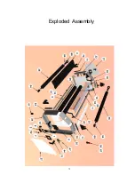
his section contains reference drawings and a parts list to assist you when ordering parts for your laminator.

The drawings show only those parts that may be replaced by the dealer.

Item

Part Number

Description

Quantity

1

11108

BAR, CAM PRESSURE

2

2

11109

BRACKET, CAM PRESSURE

2

3

11110

ROD, CAM

1

4

11111

TABLE, FEED

1

5

11112

HOLDER, FEED TABLE

4

6

11113

BRACKET, BEARING

2

7

11114

PLATE, BEARING

2

8

11115

BAR, ROLLER RELEASE

2

9

11116

HEATER

2

10

11117

BRACKET, HEATER GUARD, L

1

11

11118

COVER, HEATER GUARD

1

12

11119

HOLDER, BOTTOM HEATER

2

13

11120

HOLDER, TOP HEATER

2

14

11121

INSULATOR, HEATER

4

15

11122

TUBE, HEATER

2

16

11123

HOUSING, ROD

3

17

11124

BLOCK, IDLER/DRIVE

1

18

11125

IDLER

1

19

11126

ROD, LOWER IDLER

1

20

11127

ROD, UPPER IDLER

1

21

11128

LABEL, LEFT

1

22

11129

PLATE, LEFT SIDE

1

23

11130

TABLE, RUN-OFF

1

24

11131

PLATE, RIGHT SIDE

1

25

11132

END, ROLLER

4

26

11133

ROLLER, SILICONE, 35-40

2

27

11134

COVER, SIDE

2

28

11135

FRAME, LEFT SIDE CONTROL

1

29

11136

FRAME, RIGHT SIDE CONTROL

1

30

11137

FRAME, TOP LEFT

1

31

11138

FRAME, TOP RIGHT

1

32

11139

FRAME, FRONT LEFT

1

33

11140

FRAME, FRONT RIGHT

1

34

11141

FRAME, BOTTOM

2

35

11142

FRAME, BACK

2

36

11143

MANDREL, SUPPLY

2

37

11144

BAR, THERMOSTAT

1

38

11145

TUBE, ROLLER

2

39

11146

TUBE, WIRE

1

40

11148

LABEL, RIGHT

1

41

11149

RUN-OFF TABLE, BACK

1

42

11150

BRACKET, HEATER GUARD, R

1

43

7310

FUSE, 1A, (MDL)

2

44

2434

FUSE HOLDER, RL40

1

45

2351

SWITCH, TOGGLE, RL40

2

46

2775

SWITCH, TOGGLE, RL40

2

47

8288

RELAY, SOLID STATE 25A DC

2

48

541

TERMINAL BLOCK, 6 STATION

2

50

4031

DIGITAL READ OUT (NEW)

1

51

1170

FEET, RUBBER, LARGE

4

52

2386

OFFSET CAM COMPLETE RL43

2

53

2332

CLAMP LEVER, RL40

1

54

2369

BUSHING, IDLER FOR RL43

4

55

6546

SWITCH, EMERGENCY STOP

2

56

10124

CONTROL, HEAT, FINISHERS

1

57

2433

FUSE, 30 AMP USA, RL40

2

58

2324

MOTOR, RL40, 180V DC 42

1

59

2735

POWER CORD WIRE, RL40

10

60

2325

CHAIN, LINK, #35 MASTER

2

11

Summary of Contents for BA-EN45

Page 1: ...OPERATING INSTRUCTIONS ENTRY 4500 Model No BA EN45 Banner American Products Inc Temecula CA...

Page 2: ...CAUTION TO AVOID ANY DAMAGE PLEASE DO NOT USE RAZORS OR SHARP OBJECTS NEAR THE ROLLERS...

Page 3: ...e Film 4 5 Mandrel Tension Adjustment 5 V Thermal Laminating 5 VI Pressure Sensitive Laminating 6 VII Coating Mount Board 6 7 VIII Mounting Laminating 7 IX Maintenance Service 8 Cleaning Rubber Roller...

Page 4: ...Entry 4500 BA EN45 Mandrel...

Page 5: ...hile the laminator heater power is on Turn rollers off and allow to cool u Do not use the laminator for other than its intended purpose u Only operate this machine if you have been properly trained an...

Page 6: ...pection Upon receipt of your Entry 4500 inspect the crate the machine and all other contents of the crate for shipping damage Damage should be brought to the immediate attention of the delivering carr...

Page 7: ...an drels replace the mandrels onto the laminator Threading the Film Figures 1 2 1 Feed the film from the top roll behind the upper idler roller and lay it over both rollers Be sure that the adhesive s...

Page 8: ...page 3 for film loading instructions 2 Set the temperatures according to the film manufacturer s recommendations for the film you have chosen A low melt film is recommended for inkjet prints Keep in...

Page 9: ...Rewind Option for Pressure Sensitive Laminating...

Page 10: ...ad the pressure sensitive film behind the upper idler roller rod 5 Peel back enough of the release liner to tape it to the empty film core on the take up mandrel Tape the liner to the back of the core...

Page 11: ...g film is loaded correctly See page 3 for film loading instructions 2 Place mounting pins in proper holes 3 Turn the TEMPERATURE CONTROL switch to the ON position 4 Set the temperatures according to t...

Page 12: ...f the top and bottom supply rolls Pull any film out of the laminator and away from the rollers 3 Carefully remove the feed table to access the rollers The feed table exposes hot and moving parts 4 Dis...

Page 13: ...djust temperature slightly laminating temperature upward Ink on print is wet Allow ink to dry thoroughly Paper is too slick Use a more matte paper Laminated item curls Top or bottom film tension Loose...

Page 14: ...disconnecting the power supply XII Warranty Return Policy Warranty Your Entry 4500 is warranted to be free of defects in material and workmanship for a period of 1 year from the date of original purc...

Page 15: ...F 1 24 11131 PLATE RIGHT SIDE 1 25 11132 END ROLLER 4 26 11133 ROLLER SILICONE 35 40 2 27 11134 COVER SIDE 2 28 11135 FRAME LEFT SIDE CONTROL 1 29 11136 FRAME RIGHT SIDE CONTROL 1 30 11137 FRAME TOP L...

Page 16: ...WIRE 18 GAUGE YELLOW 1 94 597 WIRE 18 GAUGE WHITE 1 95 1326 WIRE 18 AWG WHITE BLACK 6 96 598 WIRE 18 AWG WHITE RED 6 97 10398 CHAIN 35 BULK 5 98 7251 CORE GRIPPER MANDREL 2 99 1457 SCREW 10 24 X 1 2...

Page 17: ...Exploded Assembly 13...

Reviews: