13 mm (0.5") radius minimum bend
Emitter or
Receiver
Figure 5. Cable Clearances
9. Cut the cables to length after making sure they are routed properly.
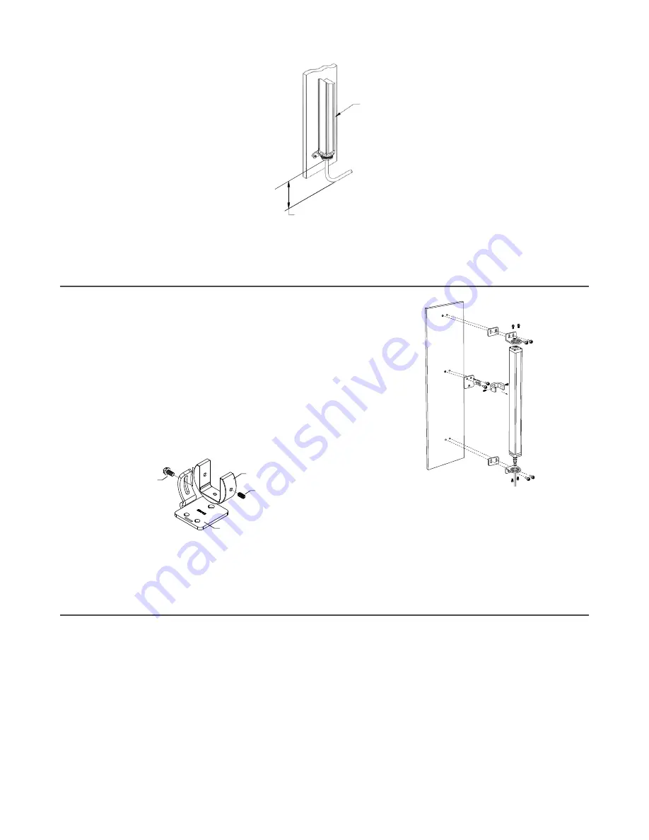
3.2 Center Bracket Mounting
Center mounting brackets must be used with long sensors, if they are
subject to shock or vibration. The sensors are designed to be
mounted with up to 900 mm unsupported distance (between
brackets). Sensors 1050 mm and longer must use a center mounting
bracket with the standard end-cap brackets.
1. Attach the center bracket to the mounting surface and use the
shim plates with the end-cap brackets to make a flush
mounting.
2. Attach the clamp loosely to the housing, using the included
M5 screws and T-nuts.
3. After the sensor is mounted to the end-cap brackets, attach
the clamp to the center bracket using a supplied M5 screw
and tighten down the clamp to the sensor housing.
Figure 6. MINI-Array center bracket mounting
Center Bracket
Clamp
Screw
Screw
(connects center
bracket to clamp)
(connects clamp
to sensor)
Figure 7. MINI-ARRAY center bracket mounting hardware
3.3 Emitter and Receiver Wiring
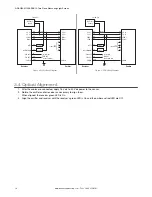
Connect the emitter and receiver cables as shown.
Receiver Output 1: (OUT1) is an open-collector transistor switch rated at 30 V dc maximum, 150 mA maximum. It is
protected against overload and short circuits.
Receiver Alarm: (ALARM) is an open-collector transistor switch rated at 30 V dc maximum, 150 mA maximum. It is
protected against overload and short circuits.
Both outputs can be configured as NPN (current sinking) or PNP (current sourcing).
A-GAGE
®
MINI-ARRAY
®
Two Piece Measuring Light Screen
www.bannerengineering.com - Tel: + 1 888 373 6767
9


