background image

7 Accessories

7.1 Cordsets

8-Pin Threaded M12/Euro-Style Cordsets with Shield

Model

Length

Style

Dimensions

Pinout (Female)

MAQDC-806

1.83 m (6 ft)

Straight

44 Typ.

ø 14.5

M12 x 1

5

4

3

2

8

1

7

6

MAQDC-815

4.58 m (15 ft)

MAQDC-830

9.14 m (30 ft)

MAQDC-850

15.2 m (50 ft)

1 = White

2 = Brown

3 = Green

4 = Yellow

5 = Gray

6 = Pink
7 = Blue

8 = Red

Note: Additional lengths available: MAQDC-875 22 m (75 ft), MAQDC-8100 30 m (100 ft), MAQDC-8125 38

m (125 ft), MAQDC-8150 46 m (150 ft).

7.2 Anti-Vibration Mounting Kits

MSVM-1

• 4 anti-vibration mounts (M4 × 0.7 × 9.5 mm)
• 8 M4 Keps nuts
• These mounts are made from BUNA-N rubber and

are more resistant to chemicals and oils.

MAVM-1

• 4 anti-vibration mounts (M4 × 0.7 × 9.5 mm)
• 8 M4 Keps nuts
• These mounts are made from natural rubber, which

are less chemically resistant than the MSVM-1

mounts, but have a greater sheer force spec at

higher temperature.

7.3 Center Mounting Bracket Kit

EZA-MBK-12-CB

Includes one center bracket and

hardware to mount to MSA Series

stands

Includes 2 shim plates for standard

end-cap brackets to allow flush

mounting

M5 mounting hardware


59

56

55

2 x Ø7

Ø8.3


A-GAGE

®

 MINI-ARRAY

®

 Two Piece Measuring Light Screen


18

www.bannerengineering.com - Tel: + 1 888 373 6767


Summary of Contents for A-GAGE MINI-ARRAY

Page 1: ...A GAGE MINI ARRAY Two Piece Measuring Light Screen Instruction Manual Original Instructions 117167 Rev C 12 December 2018 Banner Engineering Corp All rights reserved 117167 ...

Page 2: ...eceiver Wiring 9 3 4 Optical Alignment 10 4 Serial Communication 11 4 1 Serial Communication Data Format 11 4 2 Request Sensor to Scan Command Command 0 53 11 4 3 Request Sensor to Transmit all Receiver Channel State Command 0 64 11 4 4 Request Sensor to Transmit System Status Information Command 0 66 12 4 5 Request Sensor to Transmit One or Two Measurement Values Command 0 67 13 5 Specifications ...

Page 3: ...y necessary to allow its use in personnel safety applications A sensor failure or malfunction can cause either an energized or de energized sensor output condition 1 1 Models Emitter Receiver Models Array Length Y Housing Length L1 Distance Between Bracket Holes Total Beams Sensor Scan Time 1 L2 L3 Interlaced Scan 2 Straight Scan MAE616Q Emitter MAR616NX485Q Receiver 143 mm 5 6 in 231 mm 9 1 in 26...

Page 4: ...m 59 62 in 1603 mm 63 1 in 1633 mm 64 3 in 1577 mm 62 1 in 80 11 5 ms 6 0 ms MAE6616Q Emitter MAR6616NX485Q Receiver 1667 mm 65 62 in 1755 mm 69 1 in 1786 mm 70 3 in 1729 mm 68 1 in 88 12 6 ms 6 5 ms MAE7216Q Emitter MAR7216NX485Q Receiver 1819 mm 71 62 in 1908 mm 75 1 in 1938 mm 76 3 in 1881 mm 74 1 in 96 13 7 ms 7 1 ms 1 Worst case response time is twice the scan time 2 Scan time for Vehicle Sep...

Page 5: ... minimum object detection necessary to detect a trailer hitch A sensor scan involves individually enabling each emitter channel twice In effect each emitter channel fires at both its opposing receiver element and at the one beneath it The result is an interlaced optical detection pattern as shown This pattern can better detect objects within the middle third of the sensing area Along with using th...

Page 6: ...or vehicle separation detection and Output 2 for sensor health status output These outputs are rated to 150 mA and are short circuit protected 2 4 EIA 485 Interface The receiver has a serial EIA 485 interface to provide sensor profiling and system status information See Serial Communication on page 11 for additional information 2 5 Sensing Scan Time Sensing scan time is a function of the sensor le...

Page 7: ...of the diagnostic LEDs 2 Output 2 will is inactive OFF when Output 2 is configured for Alarm Health Status 3 The condition can be transmitted to the monitoring system via the EIA 485 interface see Request Sensor to Transmit System Status Information Command 0 66 on page 12 2 10 Marginal Alignment Dirty Lens Detection When the received light signal drops below a predetermined threshold the receiver...

Page 8: ...eceiver in their mounting brackets see Figure 3 on page 8 2 Position the red lenses of the two units directly facing each other The connector ends of both sensors must point in the same direction 3 Measure from one or more reference planes such as the floor to the same points on the emitter and receiver to verify their mechanical alignment If the sensors are positioned exactly vertical or exactly ...

Page 9: ...mounted to the end cap brackets attach the clamp to the center bracket using a supplied M5 screw and tighten down the clamp to the sensor housing Figure 6 MINI Array center bracket mounting Center Bracket Clamp Screw Screw connects center bracket to clamp connects clamp to sensor Figure 7 MINI ARRAY center bracket mounting hardware 3 3 Emitter and Receiver Wiring Connect the emitter and receiver c...

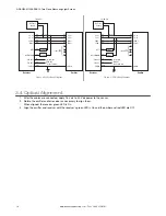
Page 10: ...IA 485 EIA 485 SHIELD SHIELD P S V P S V SYNC SYNC Receiver Emitter Load 1 Load 2 DC Power Supply to external EIA 485 device terminal no connection Figure 9 PNP Wiring Diagram 3 4 Optical Alignment 1 After the cables are connected apply 16 V dc to 30 V dc power to the sensor 2 Rotate the emitter and or receiver as necessary to align them When aligned the receiver green LED is On 3 Align the emitte...

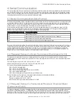
Page 11: ... equal to four The actual data bytes follow the byte representing the number of data bytes The check sum is a two byte value that is calculated by summing the previous bytes in the string Once the sum is known then a one s complement of the sum is calculated and used as the string check sum value Examples are given in the description of each command 4 2 Request Sensor to Scan Command Command 0 53 ...

Page 12: ... optical channels 26 31 are clear The last two bytes are the check sum in low byte high byte order 4 4 Request Sensor to Transmit System Status Information Command 0 66 Use this command to extract information about the sensor The information that can be received includes the following six data bytes Number of emitter channels First emitter failed channel Number of receiver channels First bad recei...

Page 13: ... of 15 light channels are blocked Transmit string to sensor 0 F4 0 41 0 67 0 00 0 63 0 FE Receive string from sensor 0 F4 0 41 0 67 0 04 0 14 0 00 0 0F 0 00 0 3C 0 FE This receive string is interpreted as follows 0 F4 is the start of header byte 0 41 is the sensor identification byte 0 67 is the command requesting the sensor measurement information 0 04 is the number of data bytes 0 14 0 00 is the...

Page 14: ...roper operation Receiver Green sensors aligned 3x excess gain Yellow marginal alignment 1x 3x excess gain Red sensors misaligned or beam s blocked Environmental Rating NEMA 4 13 IEC IP65 UL Type 1 enclosure Construction Aluminum housing with black anodized finish acrylic lens cover Controller Programming Via EIA 485 to Banner Sensors GUI software Emitter Receiver Range Sensors 1220 mm 4 ft long 16...

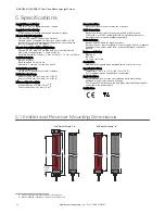
Page 15: ...16Q Emitter MAR3616NX485Q Receiver 993 mm 39 1 in 1024 mm 40 3 in 967 mm 38 1 in MAE4216Q Emitter MAR4216NX485Q Receiver 1146 mm 45 1 in 1176 mm 46 3 in 1119 mm 44 1 in MAE4816Q Emitter MAR4816NX485Q Receiver 1298 mm 51 1 in 1329 mm 52 3 in 1272 mm 50 1 in MAE5416Q Emitter MAR5416NX485Q Receiver 1451 mm 57 1 in 1481 mm 58 3 in 1424 mm 56 1 in MAE6016Q Emitter MAR6016NX485Q Receiver 1603 mm 63 1 in...

Page 16: ...on 11 9 mm 0 47 24 6 mm 0 97 57 2 mm 2 25 44 5 mm 1 75 R 6 4 mm 0 97 10 2 mm 2 0 40 Full R 4 38 1 mm 1 5 4 8 mm 2 0 19 3 8 mm 0 15 6 4 mm 0 25 QD End Non QD End ø 30 5 mm ø 1 2 ø 13 2 mm ø 0 52 ø 6 8 mm 2 ø 0 27 3 0 mm 0 12 53 8 mm 2 12 A GAGE MINI ARRAY Two Piece Measuring Light Screen 16 www bannerengineering com Tel 1 888 373 6767 ...

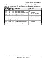
Page 17: ...N Emitter receiver pair blocked with dirty lens Clean lenses Align emitter and receiver ON ON ON Receiver error Replace receiver ON Flashing at 2 Hz OFF Degraded mode emitter receiver pair aligned Clean lenses Align emitter and receiver5 OFF Flashing at 2 Hz ON Degraded mode emitter receiver pair blocked Clean lenses Align emitter and receiver5 Flashing at 2 Hz OFF Flashing at 2 Hz Emitter is not ...

Page 18: ...nti vibration mounts M4 0 7 9 5 mm 8 M4 Keps nuts These mounts are made from BUNA N rubber and are more resistant to chemicals and oils MAVM 1 4 anti vibration mounts M4 0 7 9 5 mm 8 M4 Keps nuts These mounts are made from natural rubber which are less chemically resistant than the MSVM 1 mounts but have a greater sheer force spec at higher temperature 7 3 Center Mounting Bracket Kit EZA MBK 12 CB...

Page 19: ...nth Avenue North Minneapolis MN 55441 USA Website www bannerengineering com Phone 1 888 373 6767 For worldwide locations and local representatives visit www bannerengineering com A GAGE MINI ARRAY Two Piece Measuring Light Screen www bannerengineering com Tel 1 888 373 6767 19 ...

Page 20: ...OR SPECIAL DAMAGES RESULTING FROM ANY PRODUCT DEFECT OR FROM THE USE OR INABILITY TO USE THE PRODUCT WHETHER ARISING IN CONTRACT OR WARRANTY STATUTE TORT STRICT LIABILITY NEGLIGENCE OR OTHERWISE Banner Engineering Corp reserves the right to change modify or improve the design of the product without assuming any obligations or liabilities relating to any product previously manufactured by Banner En...

Reviews: