Alone
ID-NET
Master
STP-M12D-4xx
MQDEC-1703SS-DB25
Alone
Alone
Host
Switch
ID-NET
Slave #2
ID-NET
Slave #1
Phase
Mode
External
Trigger
Continuous
Mode
1. Ethernet TCP/IP Server 1
2. ID-NET (up to 32 devices, max network extension of 1000 m)
3. Main Serial Interface (RS232 or RS422 Full-Duplex)
4. Aux Serial Interface (RS232)
= Pass-Through Input channel
= Output channel
TCNM-ACBB1
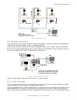
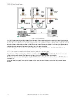
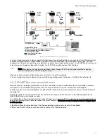
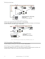
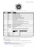
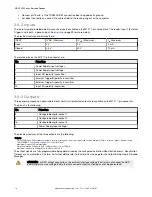
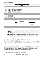
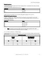
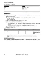
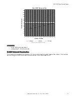
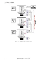
Figure 15. ID-NET Multidata Layout (Pass-Through)
In a Pass-through layout each device supports multiple pass-through configurations to accept input from different devices
on different channels (Master reader, above). However, ID-NET Slave readers are not required to have a pass-through
configuration if they do not need to receive data from an input channel (right reader, above). The ID-NET Master always has
at least one pass-through configuration to collect the ID-NET Slaves data and send it to the Host.
Note: Slave devices cannot receive data from a pass-through ID-NET input channel and Master devices
cannot send data on an ID-NET output channel.
All devices always support multiple output channels (that is, for data monitoring).
In a Pass-through layout each device can have a different operating mode: Continuous, One Shot, Phase Mode, etc.
3.5.5
ID-NET
Synchronized Network
When the device is working Synchronized, the ID-NET connection is used to collect data from several readers to build a
multi-point or a multi-sided reading system; there can be one Master and up to 31 Slaves connected together.
The Slave readers are connected together using the ID-NET interface. Every slave reader must have an ID-NET address in
the range 1-31.
The Master reader is also connected to the Host on one of its communication channels. In the following examples the
RS232/RS422 main serial interface is used.
For a Master/Slave Synchronized layout the External Trigger signal is unique to the system; there is a single reading phase
and a single message from the Master reader to the Host computer. It is not necessary to bring the External Trigger signal
to all the readers.
In the Master/Slave Synchronized layout the Master operating mode can only be set to Phase Mode.
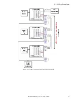
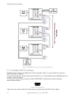
The Main and ID-NET interfaces are connected as shown in the following figures.
ABR 7000 Series Barcode Reader
www.bannerengineering.com - Tel: + 1 888 373 6767
15


