17
11
1
10
16
9
8
15
7
6
14
5
4
13
3
12
2
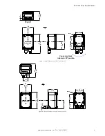
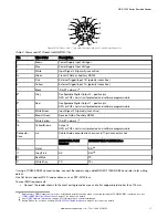
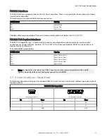
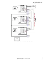
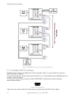
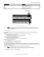
Figure 18. M12/Euro-style 17-pin male Communications, I/O, and Power Connector
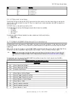
Table 2: Power and I/O Pinouts for MQDC2S-17xx
Pin
Wire Color
Description
1
Brown
Power Supply Input V
2
Blue
Power Supply Input Voltage -
3
White
Input Signal 2 B (polarity insensitive)
4
8
Green
Transmit Data of Auxiliary RS232
5
Pink
External Trigger/Input 1 B (polarity insensitive)
6
Yellow
External Trigger/Input 1 A (polarity insensitive)
7
Black
ID-NET n
9
8
8
Gray
Configurable Digital Output 2 - positive pin
NPN or PNP short circuit protected and software programmable
9
8
Red
Configurable Digital Output 1 - positive pin
NPN or PNP short circuit protected and software programmable
13
White/Green
Input Signal 2 A (polarity insensitive)
14
8
Brown/Green
Receive Data of Auxiliary RS232
15
White/Yellow
ID-NET network -
9
16
Yellow/Brown
Output 3
NPN or PNP short circuit protected and software programmable
Connector
Case
n/a
Cable shield connected to chassis and 17-pin connector shell
RS232 Main Serial
Interface
RS422 FD Main Serial Interface
10
Violet
-
RX-
10
11
Gray/Pink
RX
RX+
10
12
Red/Blue
-
TX-
17
White/Gray
TX
TX+
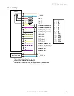
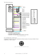
If using a TCNM-ACBB1 connection box, connect the reader using cable MQDEC-1703SS-DB25 and refer to for writing
details.
Use Cat 5e or superior M12 D-code cables, such as STP-M12D-4xx.
To meet EMC requirements:
• Connect the reader chassis to the plant earth ground by means of a flat copper braid shorter than 100 mm
8
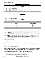
Referenced to GND; Outputs become opto-isolated and polarity sensitive when connected through the TCNM-ACBB1 connection box. See
TCNM-ACBB1 Electrical Connections
on page 21 for connection details.
9
See
on page 25 for information on resister termination.
10
If using RS422, do not leave floating. See
on page 23 for connection details.
ABR 7000 Series Barcode Reader
www.bannerengineering.com - Tel: + 1 888 373 6767
17

