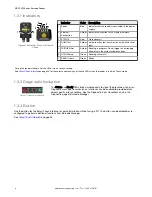
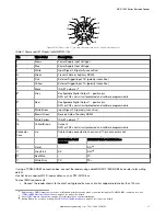
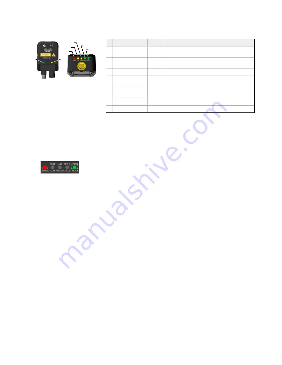
1.3.1 Indicators
3
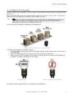
4
5
6
7
1
2
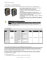
Figure 3. Indicators—Back and Top of
Device
Indicator
Color
Description
1 Power
Blue
Indicates that the reader is connected to the power
supply
2 Ethernet
Connection
Amber
Indicates connection to the Ethernet network
3 STATUS
Red
No read result
4 COM/Test
Amber
Active result output transmission on the Main serial
port
5 TRIGGER/Aim
Amber
Reading in progress. Do not trigger a new reading
attempt until the current attempt finishes
6 GOOD/Setup
Green
Reading successful
7 READY/Learn
Green
Ready
During the reader startup, all of the LEDs turn on for one second.
See
on page 36 for the colors and meanings of the five LEDs when the reader is in Smart Teach mode.
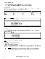
1.3.2 Diagnostic Indication
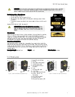
Figure 4. Diagnostic Indicators
The Status and Ready LEDs blink simultaneously to signal the presence of an error.
Diagnostic message transmission on interfaces can be enabled to provide details
about specific error conditions. See the Diagnostic Error Conditions chart in the
Diagnostic page of Barcode Manager.
1.3.3 Button
Use the button for the Smart Teach interface for quick installation without using a PC. The button can be disabled or re-
configured to perform additional functions from Barcode Manager.
See
on page 36.
ABR 7000 Series Barcode Reader
6
www.bannerengineering.com - Tel: + 1 888 373 6767