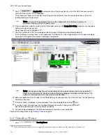
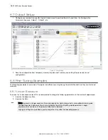
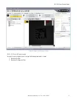


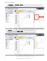
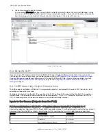

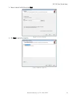
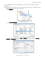
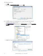
3. Click on the relevant Industrial Protocol.
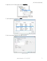
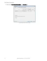
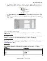
In this example, Message 2 has been linked to the EtherNet/IP Industrial Protocol. The data from Message 2 will be
sent, as an ASCII string, to the ABR Industrial Protocol output data registers. Arrows should be drawn automatically
from the messages to the Industrial Ethernet channel in the diagram in the center of the screen.
Figure 77. Data Formatting
8.2 EtherNet/IP
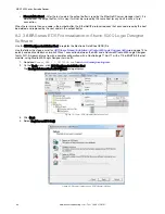
If you are using a PLC programmed by Rockwell Studio 5000 Logix Designer software version 20 or later, such as the
ControlLogix or CompactLogix series, you should be able to skip to
ABR Series EDS File Installation in Studio 5000 Logix
on page 68 and configure your PLC using the EDS and AOI files. Users of other controllers may have
ABR Assembly Object Descriptions
Configuring the ABR for Ethernet/IP in Barcode
on page 67.
8.2.1
ABR
Assembly Object Descriptions
The ABR reader is controlled via EtherNet /IP using assembly objects. From the point of view of a PLC, there is one input
assembly and one output assembly
The Originator (client) of the EtherNet /IP connection is the PLC. The Target (AKA server) of the EtherNet /IP connection is
the ABR reader. The direction of communication can be described as T > O or O > T (sometimes also shown as T2O or
O2T). The following tables list the data contained in all of the ABR assembly instances.
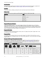
Inputs to the Sensor (Outputs from the PLC)
PLC Assembly Instance 113 (0×71) - 3 Registers (Sensor Inputs/PLC Outputs) O > T
Data transfer direction: Originator (PLC) to Target (ABR). Assembly instance 113 is the data used to control the flow of result
message strings from the ABR and pass 8 discrete input bits for control options such as triggering image acquisitions.
WORD#
WORD NAME
DATA TYPE
0
Last Item Sequence Number
8-bit integer
1
Output Bits
8-bit integer
2
Last Fragment Sequence Number
8-bit integer
ABR 7000 Series Barcode Reader
64
www.bannerengineering.com - Tel: + 1 888 373 6767


