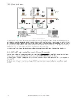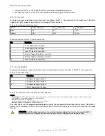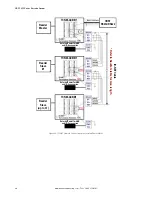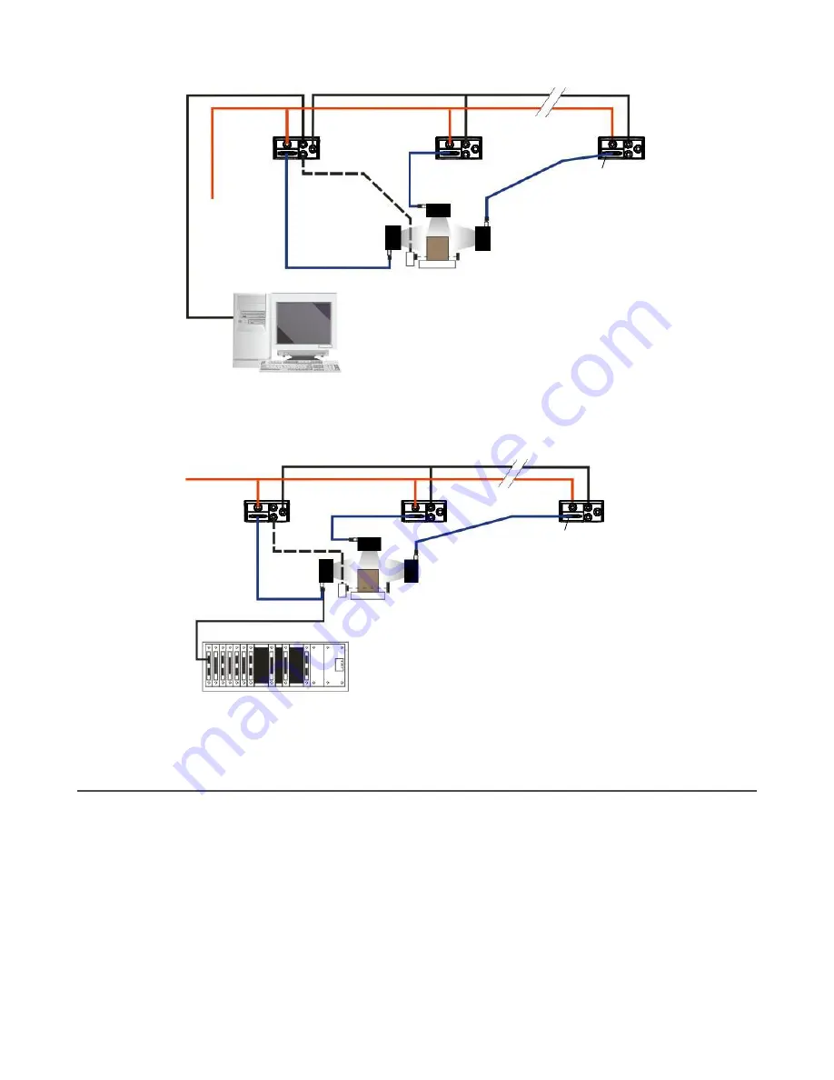
ID-NET
Synchronized
Slave #n
ID-NET
Synchronized
Slave #1
ID-NET
Synchronized
Master
Host
Power
1. Main Serial Interface (RS232 or RS422 Full-Duplex)
2. External Trigger
3. ID-NET (up to 16 devices - practical limit)
TCNM-ACBB1
Figure 16. ID-NET Synchronized Layout
All devices always support multiple output channels (that is, for data monitoring).
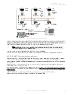
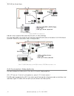
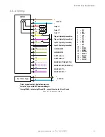
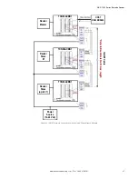
The same configuration can be made to a Host using the on-board Ethernet interface to the Master. The TCP/IP Ethernet
and ID-NET interfaces are connected as shown in the figure below.
ID-NET Synchronized
Slave #n
ID-NET Synchronized
Slave #1
ID-NET
Synchronized Master
Power
1. TCP/IP on-board Ethernet Interface
2. External Trigger
3. ID-NET (up to 16 devices - practical limit)
Host
TCNM-ACBB1
Figure 17. ID-NET Synchronized Layout with Master on-board TCP/IP Ethernet Interface to Host
3.6 Connector Descriptions
The connector pinouts and notes given in this section are for typical cabling applications.
3.6.1 Power, Communications, and I/O Connector
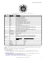
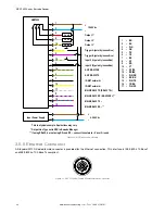
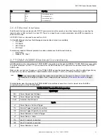
The ABR reader is equipped with an M12 17-pin male connector for connection to the power supply, serial interfaces, and
input/output signals. The details of the connector pins are indicated in the following table.
ABR 7000 Series Barcode Reader
16
www.bannerengineering.com - Tel: + 1 888 373 6767

