Banner AG4 Series Safety Laser Scanner
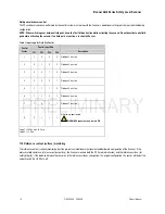
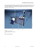
Once the Scanner is configured, switching over or “activating” the individual field pairs is controlled by the 4 FP input lines on the X1 plug
(See
table 1 Input Logic for Field Pair Control).
The rules for when each FP can be deactivated must be thoroughly analyzed during the machine risk
assessment. Machine braking distances, system response time, machine stop time and other factors that influence the Separation Distance
calculations must be considered in order to use the Field Pair switchover function safely.
WARNING . . . PROTECTIVE FIELD PAIR SWITCHING
Field Pair Switching is used to temporarily suspend or change the safety output control authority of a Protective/warning field
pair and must be performed in a way that does not put personnel at risk. Follow the guidelines listed here when changing the
active Field Pair:
Use one or more diverse redundant sensors or switches to initiate a Field Pair change
Make sure (via supplemental safe guarding) that an inactive Protective Field Pair does not create access to a hazard
point.
WARNING . . . FIELD PAIR SWITCHOVER CONTROL STATE 8
Field Pair switchover logic control state 8
deactivates the entire
Protective Field monitoring function of the Scanner. This
creates a condition where the Scanner safety outputs
(OSSDs) are turned ON
even if a person enters the potentially
hazardous area.
Only use Field Pair switchover state 8 when there is no
hazard exposure
for personnel.
Never
start the Scanner with switchover state 8 active.
Failure to follow these recommendations can potentially create a dangerous condition that may lead to serious injury
or death.
Product Manual
P/N 144924 05/2009
15


