Banner AG4 Series Safety Laser Scanner
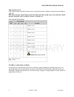
Field pair switchover control
The FP switchover sequence performed by the control system must agree with the Scanner’s operational settings which are established during
configuration.
NOTE: When switching over between field pairs, keep the first field pair active while activating the second. Do not deactivate one field
pair before activating the second; if no field pairs are active, a lockout will occur.
Table 1. Input Logic for Field Pair Control
Control Input Wire
Control
States
FP1
FP2
FP3
FP4
Description
1
1
0
0
0
Field pair 1 is active
2
0
1
0
0
Field pair 2 is active
3
0
0
1
0
Field pair 3 is active
4
0
0
0
1
Field pair 4 is active
5
1
1
1
0
Field pair 5 is active
6
1
1
0
1
Field pair 6 is active
7
1
0
1
1
Field pair 7 is active
8 0 1 1 1
All fields are deactivated
WARNING
Scanner outputs remain ON
Logic 1 = 30 Vdc max, 16 V min
Logic 0 = < 3 Vdc
1.19
Reference contour (surface) monitoring
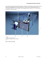
The reference contour (surface) monitoring function prevents unintentional misalignment and deliberate manipulation of the Scanner. If the
protective field contains a reference contour (surface), the Scanner monitors both the PF (for object intrusion) and the reference surface (for
safety integrity). If the distance between the sensor and the reference surfaces change from the original configuration, the sensor will detect this
and will switch the OSSDs to off.
16
P/N 144924 05/2009
Product Manual

