Banner AG4 Series Safety Laser Scanner
5. Electrical connection
WARNING . . . INTERFACING OF BOTH OSSDS
Both of the OSSDs (output signal switching devices) must be connected to the machine control so that the machine’s safety
control system interrupts the circuit to the machine primary control elements, resulting in a non-hazardous condition.
Never
wire an intermediate device(s) (e.g., PLC, PES, or PC) that can fail such that there is a loss of the safety stop function
or an unsafe, unintended suspension or defeat of the safety stop function.
The Scanner may only be connected and integrated into the machine's control system by an appropriately Qualified Person.
Observe the safety instructions and warning in the manuals
Ensure that the voltage supply and all connected input and output current circuits have safe mains isolation in acc. with IEC 742.
The safety outputs (OSSDs) are redundant
Always connect both safety outputs (OSSDs) with the machine's switch-off circuit so that they are both separately effective for
switching off the dangerous motion
Important:
The alarm outputs are not safety rated and should never be used for switching safety-relevant signals.
5.1
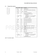
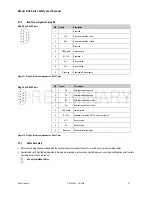
Interface Connections
The AG4 has two physical interface connections:
•
Interface X1 for connection with the control system
•
Interface X2 for connection with PC or laptop
Table 4. Interfaces
Interface
Type
Function
X1 SUB-D15
•
Power supply
•
Switching lines and signal lines
X2 SUB-D9
Configuration
interface and data interface:
•
Parameter configuration
•
PF definition and WF definition
•
Data transfer and measured value transfer
•
Diagnostics
44
P/N 144924 05/2009
Product Manual

