Banner AG4 Series Safety Laser Scanner
3. In RUN mode, observe the Scanner's status indicators to determine status, see Table 8 and Section 5.
If a
status indicator begins to flash at any time, the Scanner has entered an error or lockout condition. See
Section 5.1 for further information.
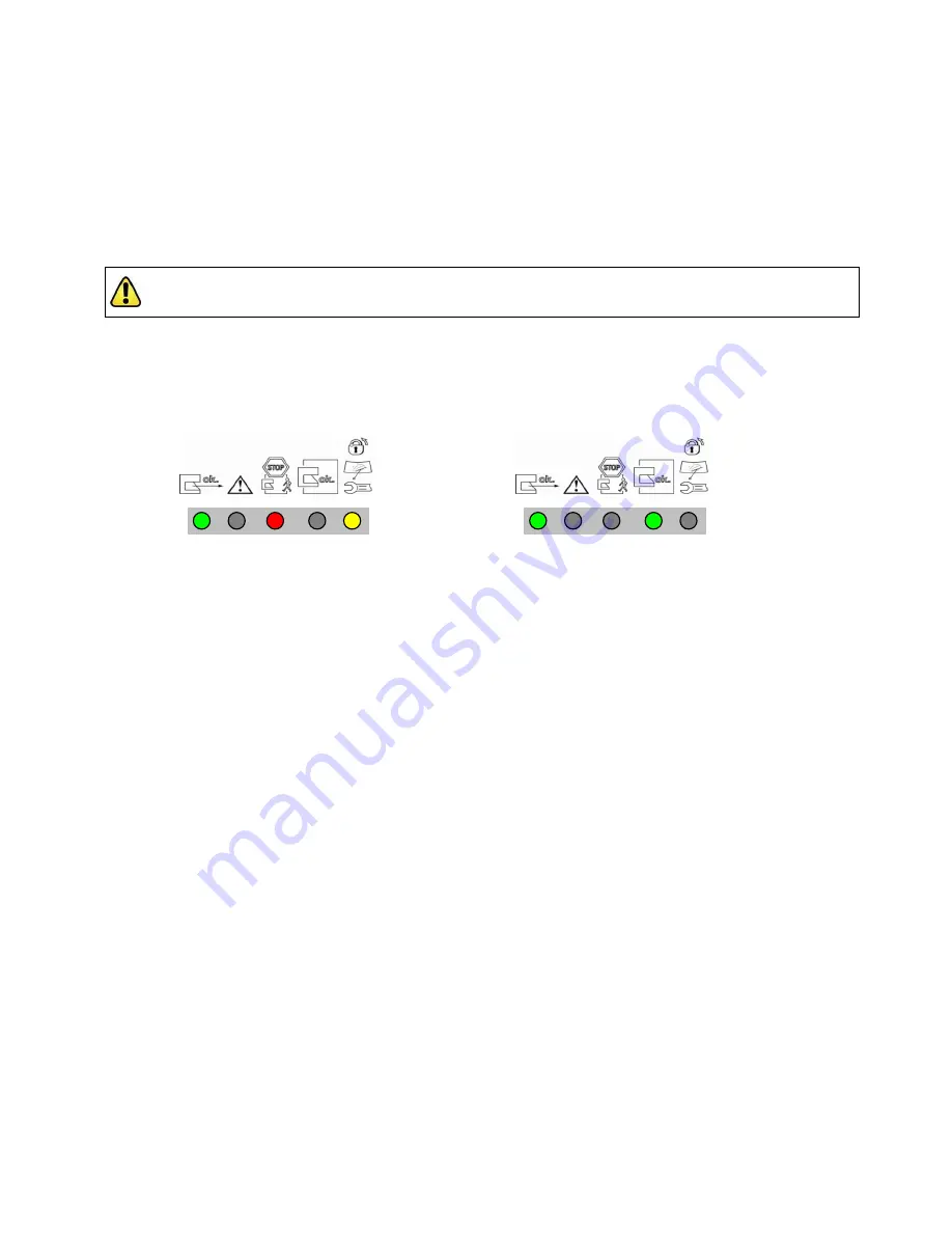
4. Ensure that the Scanner is in RUN mode, the Protective and Warning Fields are clear of intrusions, and the
AG4 LEDs indicate as shown in Figure ―a) Fields clear, OSSDs are O
N‖
or figure ―e) Fields clear, AG4 waiting
for rese
t‖
above. Then go to Section 3.6.3 Trip Test for Protective and Warning Field verification.
3.6.3 Trip Test (Protective and Warning Field Verification)
NOTE: The PC Interface can assist in monitoring the position of objects and the status of the Protective and
Warning Fields, but when possible, use the LED indicators to determine whether a field has been interrupted.
1. Ensure that the Scanner is in Run mode, the Protective and Warning Fields are clear of intrusions and the LED
indicators show:
Fields clear, AG4 waiting for reset
OR
Fields clear, OSSDs are ON
2.
If a Warning Field is used:
(with the guarded machine at rest) using the appropriate test piece (that matches
the configured/expected resolution) interrupt the Warning Field perimeter and verify LED #2 (Yellow) turns ON
as expected. Remove the test piece and verify that LED #2 turns OFF. Repeat this along the entire Warning
Field perimeter as shown in Figure 3-16. Pay special attention at needle and cone-shaped areas (see Section
3.3.1).
3. With the appropriate test piece (that matches the configured/expected resolution) interrupt the perimeter of the
Protected Field and verify LED #1 (Green) turns OFF. Remove the test piece and verify that LED #1 turns ON.
Repeat this along the entire Protective Field perimeter (see Figure 3-16 below) and verify that the configured
field:
Responds to the intrusion of the test piece
Has no unmonitored areas as described in Section 3.3.1.
Complies with the separation (safety) distance calculated in Section 3.3.4 or 3.3.5.
Note: Pay special attention at needle- and cone-shaped areas (see Section 3.3.1).
Note: For stationary applications, verify that the marking of the perimeter of the Protective Field on the
floor corresponds to LED #1. If the floor has not been marked, do so now, with the aid of the response
of LED #1.
4. Verify that the height of the Protective Field at the perimeter is at the expected level (e.g., 150 mm for mobile
applications):
Protective Fields 90º to 190º –
In at least three locations, approx. 90º apart from each other.
Protective Fields 90º or less –
In at least two locations, 90º apart from each other.
CAUTION:
Ensure that no individuals are exposed to any hazard while verifying the Protective and Warning Fields.
1
2
3
4
5
1
2
3
4
5
Buy: www.ValinOnline.com | Phone 844-385-3099 | Email: CustomerService@valin.com


