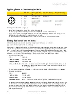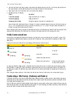
DX80...C Wiring
Wiring power to the DX80...C models varies depending the power requirements of the model.
Terminal Label Gateway, DX85 *
10 to 30V dc Powered Nodes
Battery Powered Nodes **
V+
10 to 30V dc
10 to 30V dc
Tx/+
RS485 / D1 / B / +
V-
dc common (GND)
dc common (GND)
dc common (GND)
Rx/-
RS485 / D0 / A / -
B+
3.6 to 5.5V dc
* Connecting dc power to the communication pins will cause permanent damage.
** For FlexPower devices, do not apply more than 5.5V to the gray wire.
Industrial Ethernet Wiring
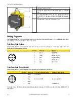
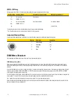
Use the 4-pin industrial Ethernet connection to connect the radio network to an Ethernet-based host system.
Wire No.
Wire Color
Description
1
White/Orange
+Tx
2
White/Blue
+Rx
3
Orange
-Tx
4
Blue
-Rx
DX80 Menu Structure
The Gateways and Nodes each have their own menu structure and options.
DX80 Gateway Set-up Menu
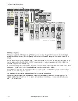
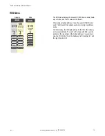
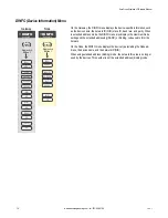
When power is applied, the DX80 begins running. The display screen auto loops through the RUN menu and communication begins
between the Gateway and Node(s). Auto looping through the RUN menu is the normal operating mode for all devices on the wireless
network.
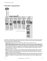
From the RUN Menu (or any menu), single-click button 1 to advance through the top-level menus. The device auto display loops through
the menu options if either of the RUN, DINFO, or FCTRY menus are selected. If the device is paused on the SITE, DVCFG, or DERR
menu options, the display does not auto loop.
To enter manual scrolling mode, double-click button 2 at the top level menu. Use the instructions shown in the chart below to navigate the
menu system. To return to the top level menus and auto display loop mode, double-click button 2 twice.
The * before the menu name indicates a top-level menu option. The () indicate submenu items.
When using Rotary Dial Addressing Mode, use the left rotary dial to set the Network ID (NID). Once changed, allow five seconds for the
devices to update to the new Network ID.
SureCross Wireless I/O Network Manual
12
www.bannerengineering.com - tel: 763-544-3164
rev. I


