The Polling Interval defines how often the Gateway communicates with each Node to verify the RF link is operating. The Gateway incre-
ments a Node’s missed message count if a Node does not immediately report back from a polling request. If a Node’s missed message
count exceeds the ‘Maximum Missed Message Count,’ the Gateway generates a timeout error in the Modbus I/O 8 register of the appro-
priate Node.
The auto-recover feature uses the ‘Re-link Count’ parameter. If enabled, the error condition heals itself if the Gateway to Node communi-
cations have successfully exchanged N-number of good polling messages. The N-number is the ‘Re-link Count,’ or the number of mes-
sages required to re-establish a RF link.
When the Node’s ‘Gateway Link Failure’ flag is set and the Gateway determines a timeout condition exists for a Node, any outputs linked
from the failing Node are set to the user-defined default state. Each Node has a ‘Gateway Link Failure’ flag that can be set or cleared
depending on the particular application.
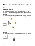
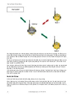
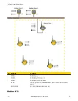
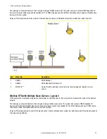
In the sample system shown, the communication link between the Gateway and Node 1 has failed. Node 2 must have its ‘Gateway Link
Failure’ flag set to allow its outputs that are linked to Node 1 are set to the defined default state when the communication link between
Node 1 and the Gateway fails.
Node Link Failure
A Node Link Failure may be determined by the polling interval or the out-of-sync timing.
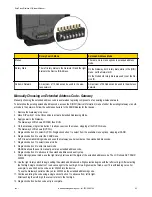
When a Node detects a communications failure with the Gateway and the ‘Node Link Failure’ flag is set, the output points are set to the
user-defined states and the inputs are frozen. When output points are set to their default states because of an error condition, only the
Gateway can clear the error condition and resume normal operation. The front panel buttons or the Gateway’s register I/O 15 clear error
conditions.
SureCross Wireless I/O Network Manual
rev. I
www.bannerengineering.com - tel: 763-544-3164
49

